LED Channels
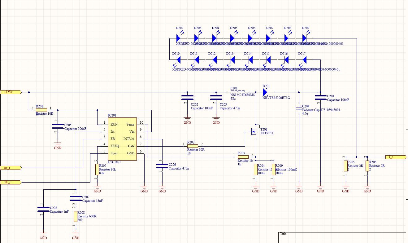
The lamp uses three LED channels, whose currents can be controlled individually. Each LED channel has a LTC1871 switching controller, a power MOSFET, a shottky diode and a coil, which form a boost converter. The LEDs are wired in series, and two parallel 2Ohm resistors are used to measure LED current.
NOTE: This schematic contains an error. Place a 1Mohm resistor (or even a high- impedance voltage divider) in front of the "RUN" pin, otherwise, the LTC1871 won't work. I overlooked this during the design, but it was an easy fix.

Overall Schematics
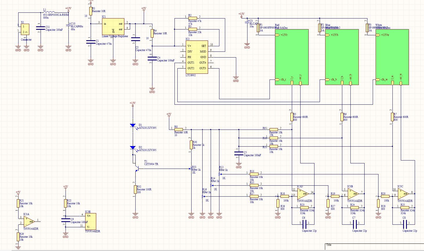
All boost converters derive their clocks from a LTC6902 spread-spectrum clock generator. I use this chip in 4-phase configuration, of which 3 are utilized by the switching regulators. The free-running clocks of the switching regulator ICs must be matched closely to the LTC6902 clock, otherwise the synchronization may not work.
An operational amplifier is used to scale and shift the voltage accross the 1Ohm LED shunts, to match the FB pin voltages of the LTC1871 ICs.
NOTE: R22 should be 10R, not 10k.

I use an external controller to monitor the lamp. It is switched off in case of an overtemperature or fan failure. Those schematics may follow later.
 t.oster92
Discussions
Become a Hackaday.io Member
Create an account to leave a comment. Already have an account? Log In.