 Yin Zhong
Full Arduino sketch (works on Due): https://gist.github.com/summivox/cfbcb8d309d416cefc3c0df10379339f
Interface with Shifter
This unit is kinda special as it can act as either an H-pattern or a sequential shifter:
- The H-pattern mode should be presented as 1 button for each gear: 7 forward and 1 reverse. Neutral is represented by all buttons released.
- The sequential mode should be presented as 2 buttons: shift up and shift down.
- A push/pull lever near the bottom of the base selects the mode.
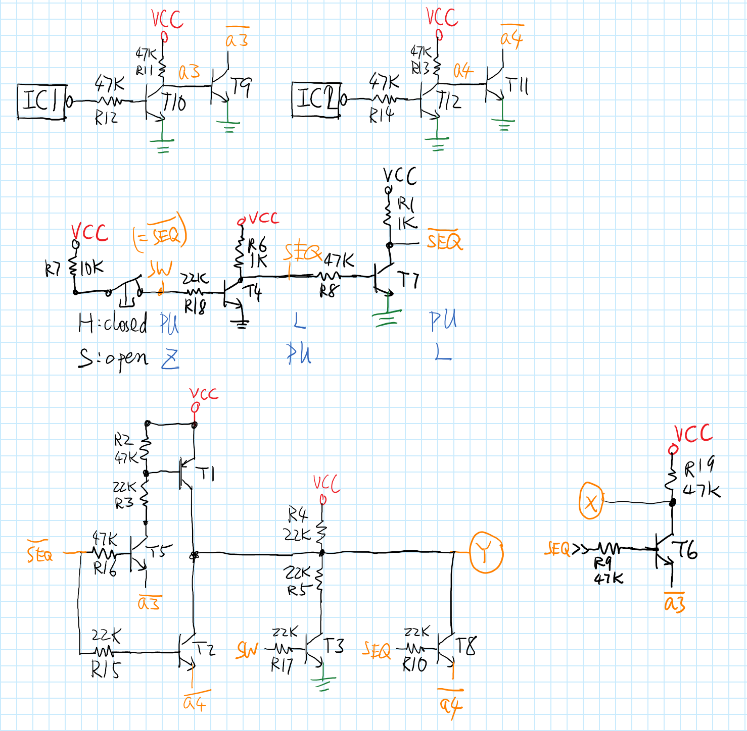
After some googling I found a legit looking pinout / schematic in a forum post:
- GND
- low = H-pattern, high = sequential
- internally shorted to pin 2
- X axis (H-pattern); lever push (sequential)
- Y axis (H-pattern); lever pull (sequential)
- VCC
Pin numbers are for RJ12 (6P6C).
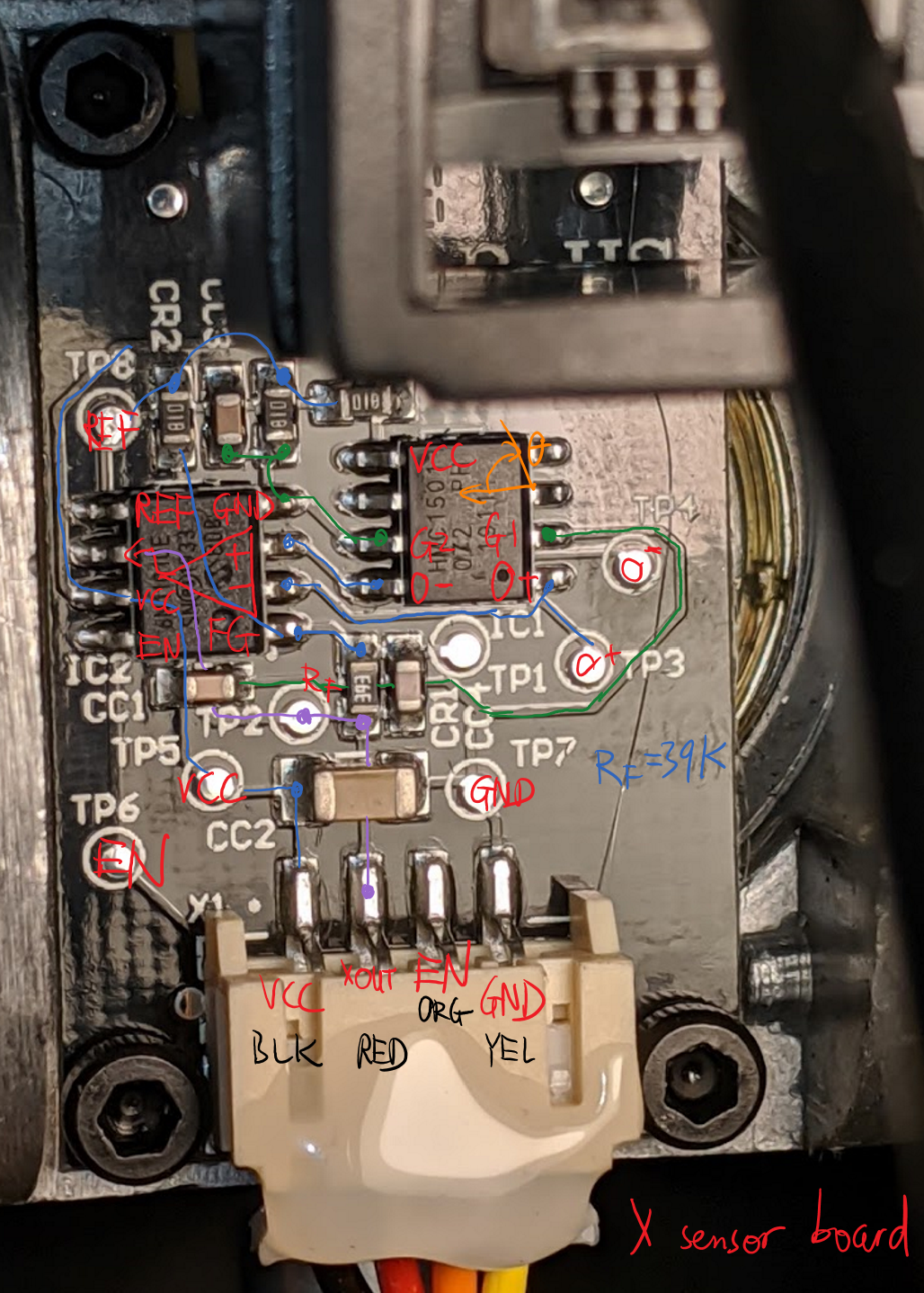
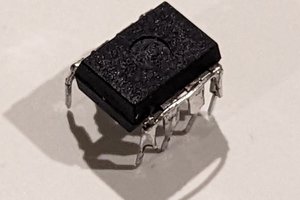
Just to be safe though, I opened the shifter up to make sure that VCC and GND matches the pinout listed above. The trick is to locate the power and ground pins on ICs:
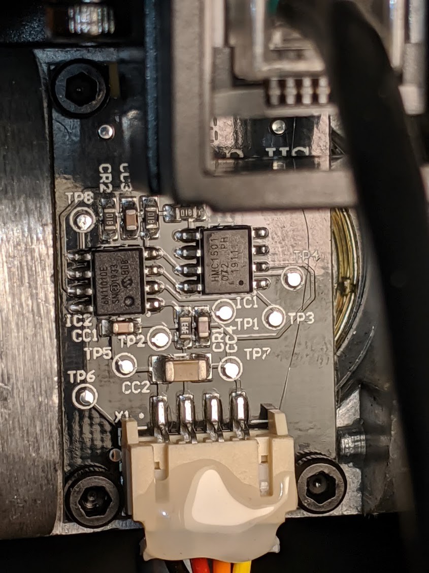
The chip on the left is an MCP6N11-010, an amplifier. Knowing its pin 4 is GND and pin 7 is VCC, some continuity checks is enough to confirm the pinout.
While I don't have any RJ12 jacks/plugs around, the shifter does come with two cables --- one RJ12-to-RJ12 for connecting the shifter to "modern" Fanatec wheels, and one RJ12-to-PS/2 for "legacy" wheels. I don't have any so I decided to turn the legacy cable into a pigtail. Well, not quite a pigtail --- I happen to have an IDC header around so I just shoved the individual wires into the header and clamped it down.
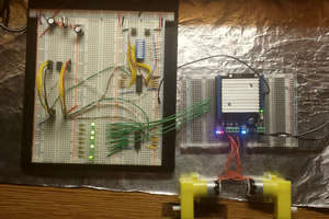
Now with a cable, I fired up my bench power supply and scope to inspect the outputs:
- In the H-pattern mode, X axis continuously tracks the left-right angle of the stick, while the Y axis has 3 discrete states: forward, center, and backward.
- In the sequential mode, both "X axis" and "Y axis" outputs are active-low discrete signals (simple button). Pushing the stick makes "X" go low; pulling makes "Y" go low.
Sounds pretty simple. I slapped on some naive debouncing logic and logged everything through serial. Looks to be working.
USB HID gamepad on Arduino Due
I simply pulled in the Arduino Joystick Library. It works out of the box.
BTW: This is why I am reluctant to use STM32, my all-time favorite MCU series, for anything USB. Instead of over-complicated proprietary "middle-ware" on under-documented hardware, I'd rather have a simple open-source library that gets the shit done.
Limitations
I did not include any calibration capability for the H-pattern mode. Everything is hard-coded. While this is okay for the Y axis since it only has 3 states (high, mid, low), the X axis is more crowded and MIGHT be different from unit to unit. If the hard-coded constants are not good enough for you, simply upload an analog input logger sketch and figure out the correct values yourself.


 Shranav Palakurthi
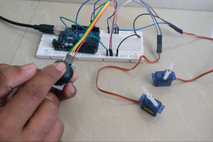
 Mild Lee Interested
i followed your project using a generic leonardo r3 and im not able to get any input read. i changed the first line from cstdint to stdint.h, and commented out analogreadresolution as they were both causing errors for me. i then followed your pinout putting P2 to A2, P4 to A0, P5 to A1, P1 to GND P6 to 3.3V. i uploaded the sketch fine, and my pc detects the leonardo as a usb game pad and sees the shifter inputs as buttons, but input from the shifter is not doing anything. if you could provide any guidance on if i made an error with the pins, or if i need to use readresolution somehow, it would be much appreciated!