 Ben Jacobs
Description
After the individual subsystems were tested and validated, the next step was to construct a full-system prototype. This was the first step of the project (officially known as the system integration) that had to be completed off-campus due to the worldwide pandemic. Therefore, some modifications had to be made, and some tests could not be run in a formal lab environment.
Procedure
First, a cardboard mock-up of the Hammond 1590DD enclosure we wished to use was constructed. It matched the dimensions of the actual metal enclosure (which was not yet on hand), according to dimension drawings provided on Hammond's website.
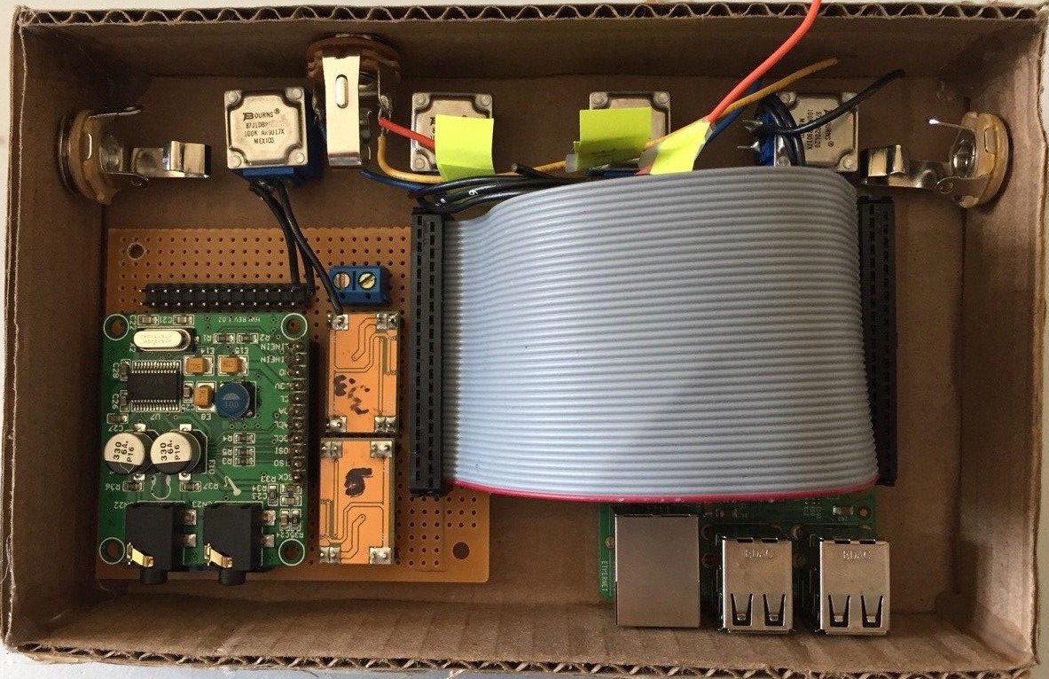
Next, using the cardboard prototype as a guide, a piece of perforated circuit board was cut down to a size that would fit in the enclosure. The ADC boards, the power supply modules, and the audio codec were laid out in a manner that minimized space consumption. Specifically, the ADC boards are located underneath the audio codec. This is not especially advised because i2c noise could leak into the audio, but this was not a problem we encountered. On issue that was encountered was having power supply noise on the audio. This was remedied by placing 470uF electrolytic capacitors across the regulated voltage outputs. In retrospect, linear regulators could've been used in place of buck-boost regulators to fully eliminate this noise issue, but at the cost of power efficiency.
A 20 pin (0.1" pitch) header was used to connect the four knobs, expression pedal input, audio input and output jacks, LED and bluetooth pairing button to the board. For a very detailed layout of this pin header and the hardware PCB, please view the Hardware PCB Schematic Diagram PDF file, which is taken from Ben Jacobs' engineering notebook.
A 40-pin IDE ribbon connector is used to connect the hardware board to the Raspberry Pi, providing the necessary i2c, SPI and GPIO connections between the two.
Result (Preliminary Prototype)
The finished prototype in the cardboard enclosure is shown below, minus the necessary wiring harness going between the jacks, knobs and pin header. Notice that the Raspberry Pi is a tight fit. In retrospect, it may have been better to use a larger enclosure size for some wiggle room.
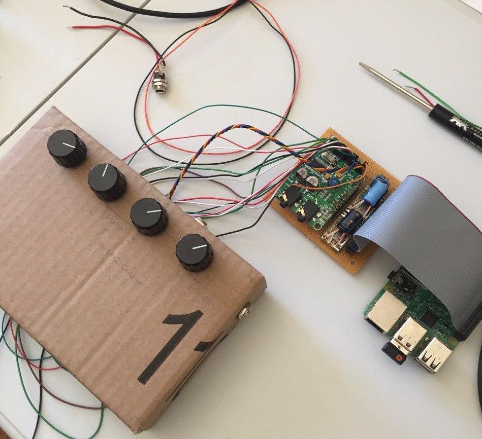
Another photo of the prototype is shown below, this time from a top view, with the internals wired into the knobs and jacks, but sitting externally on the table for testing purposes. Notice that the stomp switch has not yet been implemented, because this prototype would not support physically being stomped. In the metal version, the stomp switch will fit in the gap between the PCB and the Raspberry Pi.
![]()
Video (Preliminary Prototype Test)
Below is an informal test of the preliminary hardware prototype. This video serves as proof that the system is working, and a more complete demonstration video may be uploaded when the pedal is in a more polished state.
Upgrade to Aluminum Enclosure
Once the functionality of the cardboard prototype was confirmed, it was mailed to team member Ryan Knepel, who was in charge of the final integration into a metal enclosure. He is also scheduled to integrate the stomp switch, LED, and preamplifier circuit.
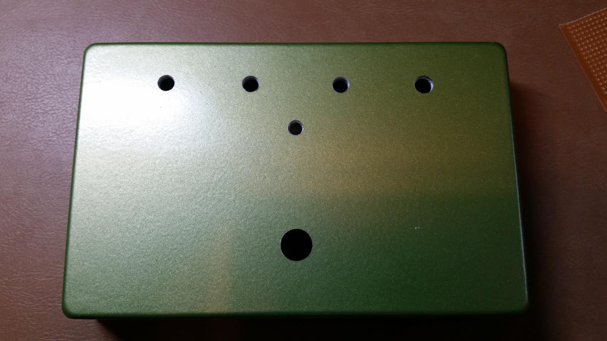
Below is a photo of the aluminum enclosure, which has been painted (a green color was not our first choice, but it sufficed because of limited access to hardware stores at the time) and drilled.
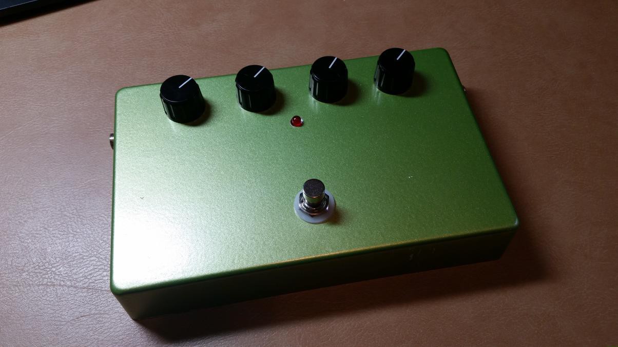
Below is another image of the aluminum enclosure, now with the various jacks, knobs other hardware elements mounted in the holes. This photo gives a good idea of how the final product will look (much more professional than the cardboard prototype!).
Discussions
Become a Hackaday.io Member
Create an account to leave a comment. Already have an account? Log In.