 benw
benwHow are the Mechanical aspects tested?
1) Simulation:
Each element of the RX-Modulus was first simulated with a force of 49N (5Kg) applied, which is quite a notable weight to apply down using your hand. For example the Adjustable Palm support was tested in its fully extended mode which is its weakest position. All elements and modules are tested in there weakest position. The part was simulated with a material property of ABS plastic which is 98% identical to the resin I'm using for this prototype.
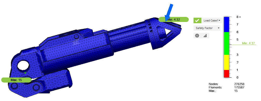
The testing showed that the part can easily support 49N (5Kg) and with a safety factor of 4.32(min) the part can support be weight of 211.68N (21.6kg) before failing. Now this is virtual so to cover all the bases all parts are then physically tested.
2) Physical Testing:
In my eyes Simulation gives me a warm feeling that at-least the part is strong virtually but nothing is better than physically testing a item. There are many ways to test this item but the testing of the Adjustable Palm support was easy all I needed was some scales.
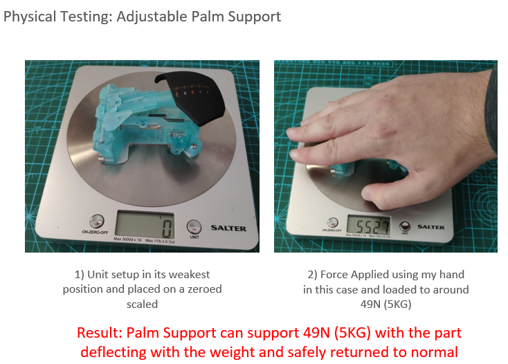
The results of the test are very promising as the deflecting due to the weight actually acts as a spring which is actually a nice feature this element has.
How are the Electronic aspects tested?
The chart below shows the basic steps we take when developing any electronic element of these project.
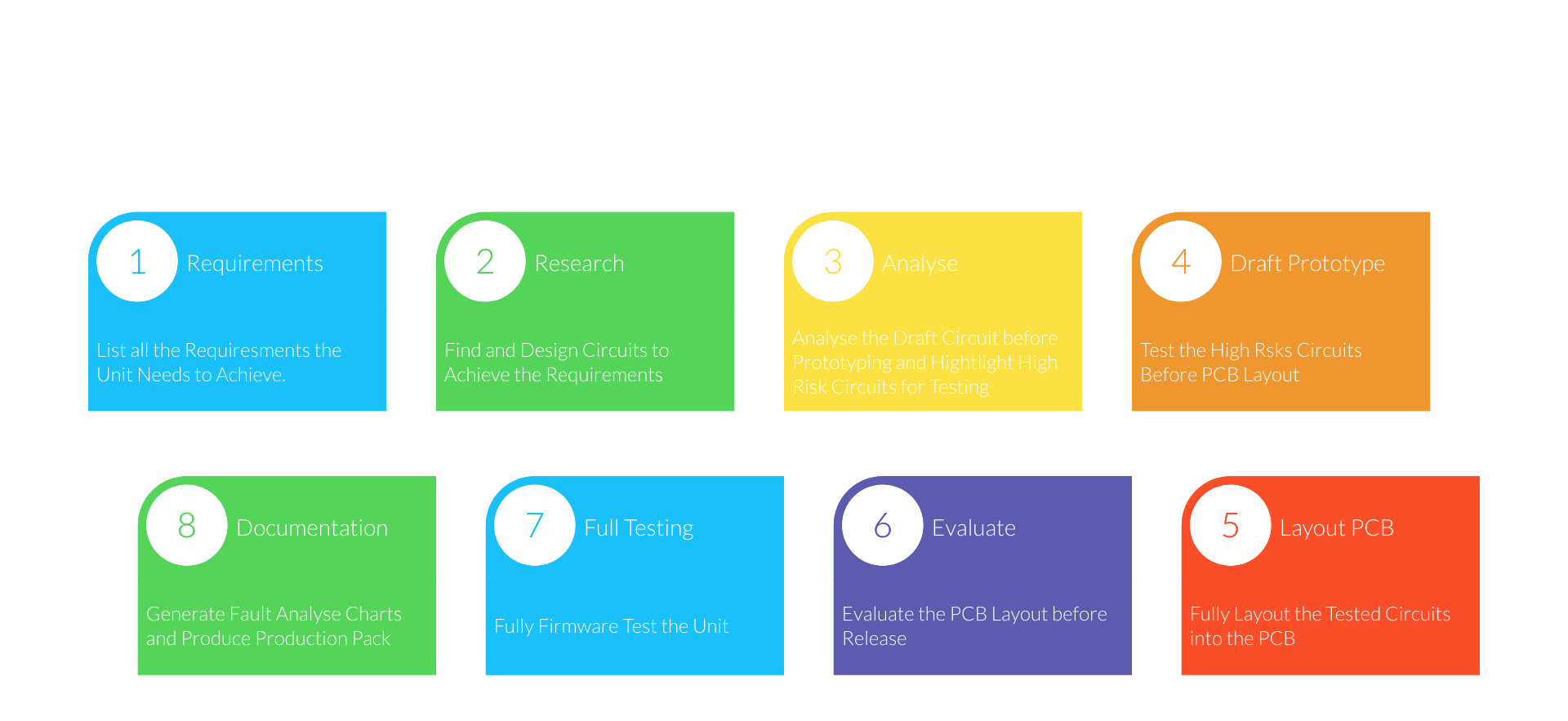
Note: If a issue is found that requires circuit fixes and new PCB's at step 7 we would jump back to step 4.
We have a whole suit of tools and equipment to help us test the electronics. For the Touch-D module the most helpful tool is the Digital Discovery (Logic Analyser). This tool would allow us to test all comm busses and ensure that all GPIO are being driven correctly.
How will the Firmware be tested?
The Digital Discovery (Logic Analyser) is also very important when doing the firmware testing. There are two methods of testing that are done these are:
1) Standalone Testing:
Standalone testing is done first with the unit, in this case the Touch-D module is driven standalone from the rest of the system. As the analyser and send and receive I2C data. We use the Digital Discovery (Logic Analyser) to pretend to be the core unit master. This gives us a stable, fast and reliable testing structure.
2) Integration Testing:
After we are happy with the Standalone testing we will then conduct Integration testing. This would be done after the Core Unit has been fully tested, if we were testing a module like the Touch-D. At this stage all performance checks are made and recorded before full release.
Documentation:
After Hardware and Firmware Testing on electronic elements all the production files will be release to ensure we have stable and known working items. At this stage will be also be creating Fault Analysis Charts to help the user fault find. There will be a basic chart as shown below that only require basic testing and fixes. An Advanced Fault Finding Chart are to be released for people that have technical knowledge and basic electronic tools and wish to fix the boards themselves.
Discussions
Become a Hackaday.io Member
Create an account to leave a comment. Already have an account? Log In.