Close
0%
0%

The nRF9160 Feather

A fully featured LTE Cat-M1 and GPS enabled Feather. It sports everything you'd expect from a Feather and more.

Similar projects worth following
Starting from
$104.00
jaredwolff has 22 orders / 0reviews
Ships from United States of America
This is The nRF9160 Feather! It's open source and ready for your project!

It's a 4 layer board with some added capabilities built in like:

- Low power RTC mode for extreme sleep
- Onboard NOR Flash
- D7 and charge status LEDs
- Oh, and an onboard linear Li-poly charger as well!

This version supports an external nano SIM. It features a U.FL connector for an external antenna. It's also capable of supporting an active GPS antenna as well!

Diagram

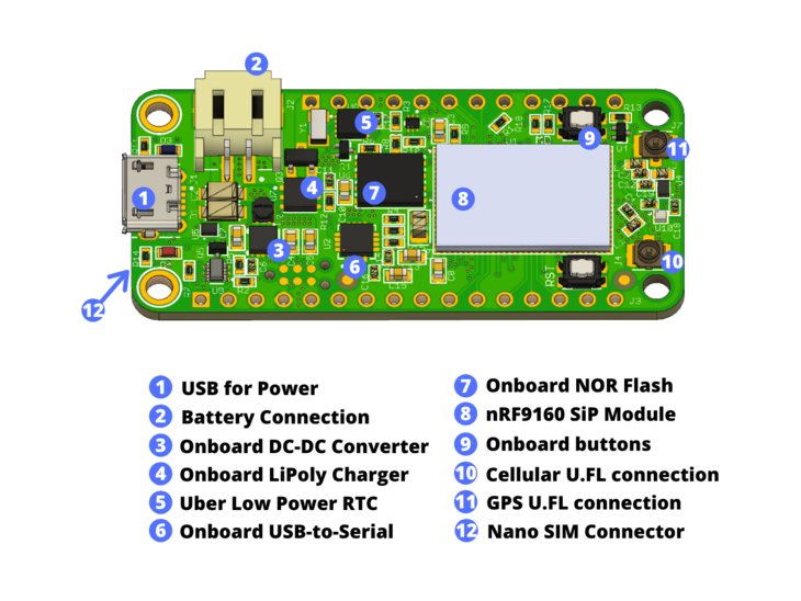
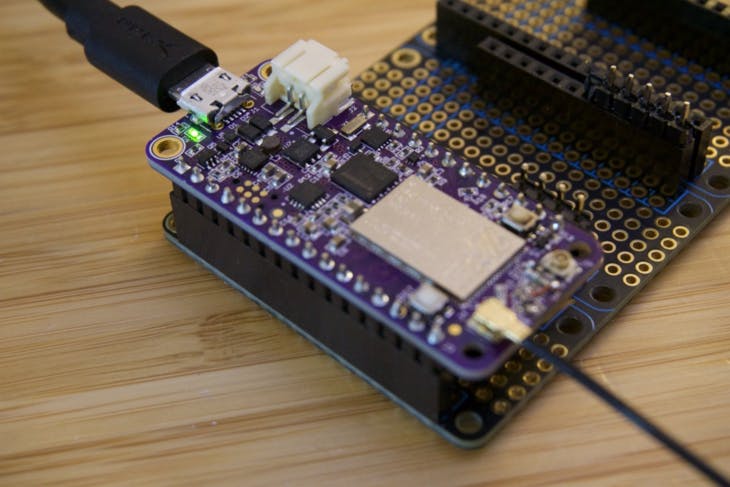
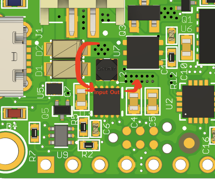
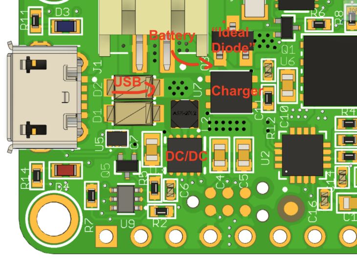
This board can be powered several ways. The most popular way to power Feather boards is by using the USB port. This board is no exception. It works well across both USB and LiPoly batteries.

The board is designed from the ground up to be power efficient at the most used power state: standby. That's right, if you're developing something that's battery powered, your most used state will usually be standby mode. As of this writing the estimated current draw in this state should be about 2µA. That's approximately 8.5 years on a 150mAH cell!

Speaking of power, this board also has a fully fledged DC/DC Buck Boost. That whether your input voltage is 5.5 or 2.8V you'll get a nice stable 3.3V at the output.

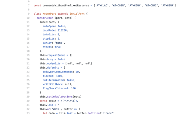
This board also sports some external flash for storing your application data. Use it with the built in support for LittleFS in Zephyr. Or, use one of your choice! What ever tickles your fancy.

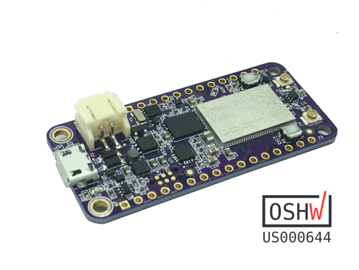
Finally, but not least, the nRF9160. I've been watching this part very carefully since the CEO had it locked in a mysterious black case years back. It's here and it's real and the module is half the price of other modules. I won't bore you with all the technical details. (Technical details get you excited? Go here.) Needless to say, it's awesome.

Technical Details

  • Nordic nRF9160*
    • Microcontroller
      • ARM Cortex M33
      • 1MB Flash
      • 256kB RAM
      • ARM® TrustZone®
      • ARM® Cryptocell 310
      • Up to 4x SPI, I2C and UART with Easy DMA
      • I2S w/ EasyDMA
      • 4x PWM with EasyDMA
      • 12bit SADC with EasyDMA
      • 2x RTC
      • PPI (Programmable peripheral interconnect) interface
    • Radio
      • Transceiver and baseband
      • 3GPP LTE release 13 Category M1 and NB1 compliant
      • 3GPP release 14 NB2 compliant
      • GPS receiver (GPS L1 C/A supported) - Active antenna only.
      • RF Transceiver for global coverage supporting bands:
        • Cat-M1: B1, B2, B3, B4, B5, B8, B12, B13, B14, B17, B18, B19, B20, B25, B26, B28, B66
        • Cat-NB1/NB2: B1, B2, B3, B4, B5, B8, B12, B13, B17, B18, B20, B25, B26, B28, B66
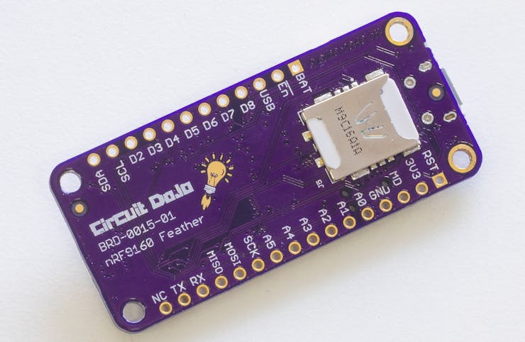
      • Supports 4FF Nano SIM
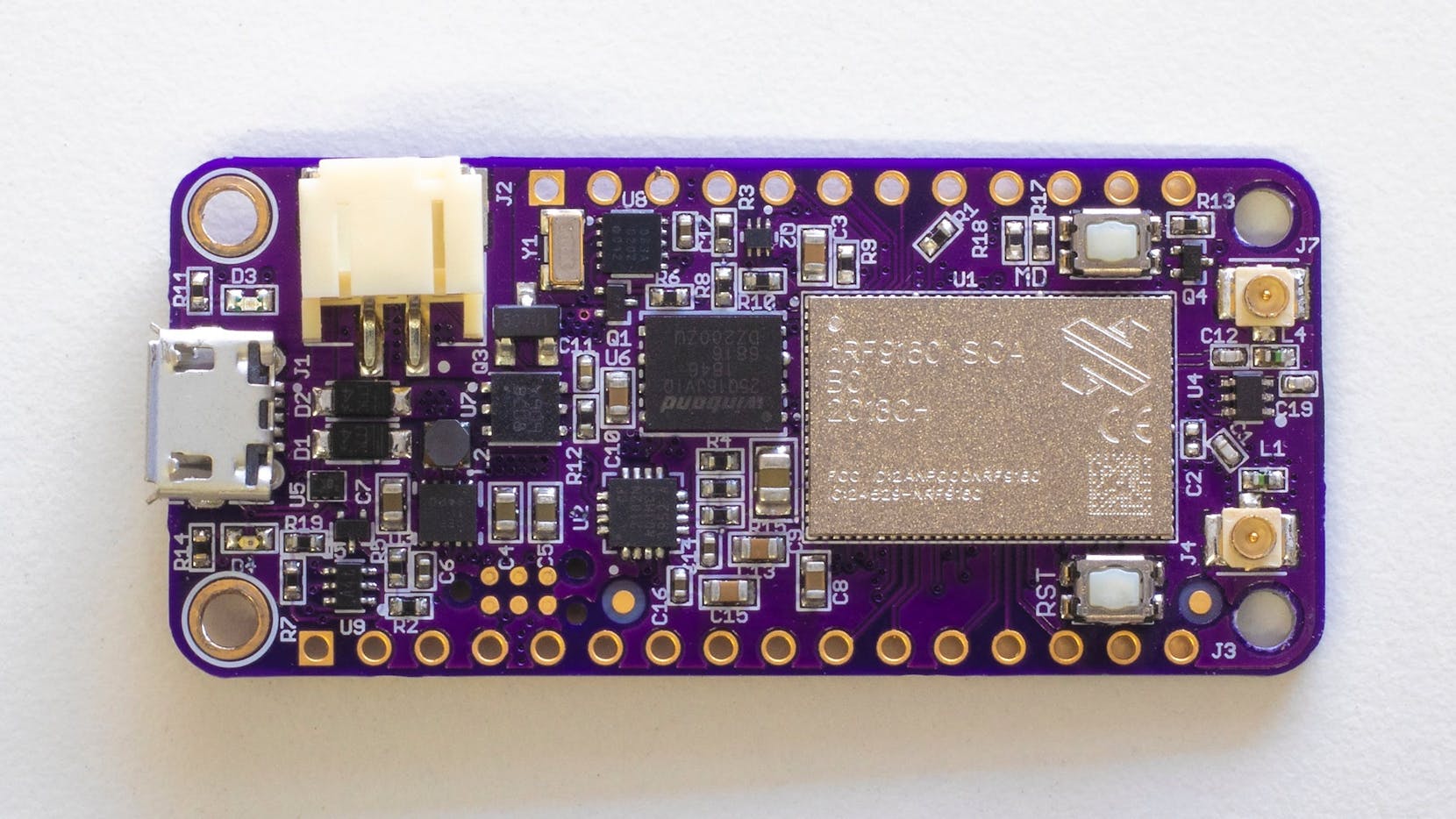
  • Micro USB connection for USB-to-Serial and DFU
  • Pre-programmed MCUBoot bootloader
  • External NOR Flash by Winbond
    • 2MB of space
    • Max bus speed of 133MHz
    • Standard SPI
  • Power supply
    • 3.3V Buck/Boost up to 0.9A of current draw
    • Operating range 2.8 to 5.5V
    • External LiPoly battery connection (JST SPH type)
    • LiPoly set to 300mA with indication
  • Programmer
    • Capable of interfacing with Jlink and CMSIS-DAP based programmers
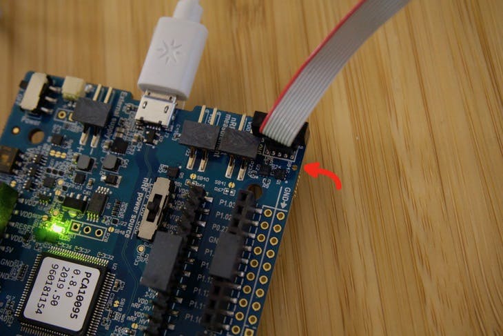
    • Use with a Tag Connect TC2030-CTX-NL over Serial Wire Debug (SWD)
  • Low Power RTC on board for time keeping and as a low power wakeup source.
  • User I/O
    • Standard feather form factor GPIOs (0.1" pitch)
    • 2x buttons (1 Reset, 1 General Purpose)
    • 1x Blue LED connected to D7
  • Antenna connections:
    • 1x U.FL for LTE with matching network
    • 1x U.FL for active GPS antennas
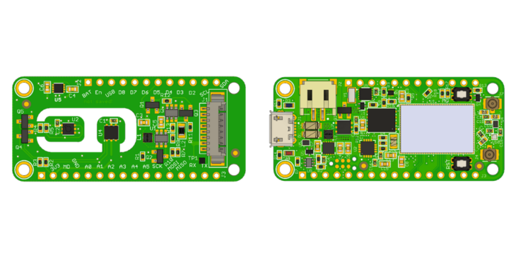
  • Feather form factor
    • 50.8mm x 22.86mm (2" x 0.9")

* nRF9160 tech specs provided from the nRF9160 Product Specification

  • 1 × nRF9160 Nordic Semiconductors nRF9160 LTE + GPS System in Package

  • The nRF9160 Feather Is Now Served

    Jared08/01/2020 at 03:43 0 comments

    I was a complete failure. My prototype wasn’t working. I spent at least an hour trying to rework a frustratingly large LTE module on an impossibly small circuit board.

    It wasn’t going to work.

    So I went back to the drawing board. I poured my years of hardware experience into a tiny form factor.

    The end product?

    Something smart. Something with LTE, NB-IoT, and GPS. Something anyone could get started with right away.

    And thus, the nRF9160 Feather was born.

    The nRF9160 Feather Video!

    The nRF9160 Feather brings all the features I’ve been craving into a familiar package. Things like low-power shutdown capabilities, built-in 4FF SIM card slot, flexible power supply, and 2MB of external flash. Plus, everything else you’d expect from Feather form factor board.

    Plus with a company like Nordic Semiconductor behind the nRF9160, I knew it would be something I’d find myself using every day. I didn’t want to be the only one though.

    Open source

    The nRF9160 Top + OSHW Cert #

    The nRF9160 Top + OSHW Cert #

    I could have been secretive about the development of the nRF9160 Feather. Instead, I wanted to share its’ story with everyone. See, the best way to learn is to see and then do. That’s how I built my very circuit board back in 2007 with nothing but some rudimentary knowledge of how EagleCAD worked.

    So please, I encourage you to check out the documentation, download the source, and start tinkering. The hardware is under the CERN v1.2 license which is fairly permissive. For more information, check out the campaign page.

    How do I use it?

    Great question.

    The nRF9160 runs on Nordic’s nRF Connect SDK. If you’re a Microsoft Visual Code user, you can check out how I got started. That way you don’t have to go through the same pain I did!

    Once you’re setup, the nRF9160 Feather works with many of the SDK examples. For example, compiling and flashing the at_client firmware is as easy as:

    cd ncs/nrf/samples/nrf9160/at_client/
    west build -b circuitdojo_feather_nrf9160ns -p
    west flash

    Where am I?

    nRF Cloud GPS Plots

    nRF Cloud GPS Plots

    The nRF9160 Feather has worked with all the active GPS antennas that I’ve tested. Simply attach one, load the firmware and go.

    I used the nrf_cloud_agps example (with some slight modifications) to track a recent jaunt around the neighborhood. You can see the path in the screenshot of nRF Cloud above. Many of you have expressed interest in tracking your personal belongings like bicycles, cars, etc. This will get you started in the right direction, fast.

    So much more

    Since the nRF9160 Feather has been added to Zephyr, you can almost use any example or sample. Many of the nRF Connect examples work with minor adjustments. Here are some of the other examples I’ve used with great success:

    nrf/samples/nrf9160/https_client - does the equivalent of an HTTP GET on https://www.google.com using SSL.

    nrf/samples/nrf9160/gps - basic GPS example with an optional SUPL library that uses Google’s SUPL server. This is a form of assisted GPS that helps get fixes much faster on cold start. (We’re talking about orders of magnitude faster.)

    nrf/samples/nrf9160/lte_ble_gateway - a great example for connecting you nRF9160 directly to other Bluetooth devices using Zephyr’s HCI Bluetooth library. It works specifically with the Thingy52. You can adapt it for other devices as well.

    nrf/samples/nrf9160/mqtt_simple - establishes a connection with a MQTT server. It subscribes to a topic and replies in an echo so a separate “pub” topic. It’s a great example to start working with an MQTT solution that may not involve AWS.

    Cellular service required

    The nRF9160 doesn’t connect to the outside world without cellular service though! Here in the states most of the carriers support LTE-M only. This includes AT&T, Sprint, and Verizon. While there are others, my tests have shown they don’t work.

    Fortunately, backers of the...

    Read more »

  • How To Add Bluetooth to your Zephyr powered nRF9160 Feather

    Jared08/01/2020 at 03:43 0 comments

    One of the cool things about Zephyr is its modularity. It’s also one of things that makes development on the platform difficult. This is especially true if you’re not use to the recursive nature of CMake or how to configure it in the first place!

    Despite these setbacks, I was able to configure the nRF9160 Feather to be used as a fully fledged Bluetooth device! In this post you’ll see some of important steps and learn from my experience of starting “from scratch.” That way you don’t have to do it all yourself!

    So without further ado, let’s begin!

    An RTOS With Some Serious Features

    Let’s start with an easy example. Then we can wade into something more.. complicated. 

    Does you project have USB? Add a few lines in your prj.conf and voilà, presto change-o, and you have a USB Console!

    Don’t believe me?

    I took a Particle Xenon I was using and got searching through the Zephyr repository. I searched for maybe a minute or two until I found the correct definitions. Fortunately. there were a few other samples in the Zephyr repo that use the same features. That made the search much easier!

    You can add this to nearly any project. Just make sure that your device has USB and that it’s definied in the Device Tree. For now we’ll assume you’re using a nRF52840.

    CONFIG_CONSOLE=y
    
    CONFIG_USB=y
    CONFIG_USB_DEVICE_STACK=y
    CONFIG_USB_DEVICE_PRODUCT="Xenon"
    CONFIG_USB_UART_CONSOLE=y
    
    CONFIG_UART_INTERRUPT_DRIVEN=y
    CONFIG_UART_LINE_CTRL=y
    CONFIG_UART_CONSOLE_ON_DEV_NAME="CDC_ACM_0"
    
    CONFIG_USB_UART_DTR_WAIT=y

    Compiling and flashing is done with these guys:

    west build -b particle_xenon
    west flash

    Then, when I plug in and start the session using screen I get some nice output:

    Things don’t always go as planned though.

    The CONFIG_USB_UART_DTR_WAIT does lock the processor from executing until the shell session has been opened. The peripheral doesn’t show up otherwise. (not exactly sure why…)

    With the above being said, the Zephyr stack is fraught with hidden APIs and documentation that is sorely lacking in some areas. Even the features I found above area not in the official Zephyr documention. You should be prepared to hit some potholes as you go along. (I’ve been hitting them for the past few weeks if that gives you any indication!)

    Fortunately, Nordic has been leading the charge in making sure that anything related to Nordic devices is as stable as possible.

    The nRF9160 Feather Does Some Tricks Too

    The nRF9160 is a fantastic little System in Package. One thing is missing though: Bluetooth. Fortunately, there’s an easy way to add it with Zephyr that works quite well. As you’ll see in the next steps, the picture I pain’t of Zephyr above isn’t all bad.

    Looking for the example code

    Examples are always a great place to start in Zephyr. The one we can start using almost immediately is the /nrf/samples/nrf9160/lte_ble_gatewaysample. This sample does everything that someone would want to do in order to connect a nRF9160 to a Bluetooth capable device.

    You’ll need to have the full ncs (Nordic’s Connect SDK) setup in order to get to it though. You can learn more about getting setup here. You can also look at my earlier post about it as well.

    Modifying the Device Tree definition

    Taking a look at the boards folder withing the sample you can see that there is an .overlayfile. This helps point which UART interface will be used for the HCI communication. The one for the nRF9160 development kit looks something like this:

    / {
    	chosen {
    		zephyr,bt-uart=&uart2;
    	};
    };
    
    &uart2 {
    	compatible = "nordic,nrf-uarte";
    	current-speed = <1000000>;
    	status = "okay";
    	tx-pin = <18>;
    	rx-pin = <17>;
    	rts-pin = <21>;
    	cts-pin = <19>;
    };

    The first part, is about choosing which interface to use. In this case they assigned the zephyr,bt-uart interface to uart2. They’ve then re-defined uart2 below. I say re-defined...

    Read more »

  • The nRF9160 Feather Connects!

    Jared08/01/2020 at 03:42 0 comments

    This week, the nRF9160 Feather got some more attention. I even got it to roll over. 😇 To top it all off, my hardware validation list is looking good!

    There’s still tons to do but it’s been a very promising start!

    In this post I’ll discuss the state of things and where hardware, firmware and more are going next.

    Let’s do this!

    What’s in the box?

    There’s a ton to Zephyr. Let’s face it, there’s an overwhelming large amount of libraries, sub-libraries, and samples. Nordic’s Connect SDK requires several different repositories to make things work.

    Here’s what a typical top level directory looks like:

    • bootloader - the MCUboot bootloader used for the nRF9160 (and other boards)
    • mbedtls - a library imported by the SDK. Used for encrypting/decrypting data
    • modules - modularized external libraries (littlefs, etc)
    • nrf - most Nordic samples live here
    • nrfxlib - the main set of Nordic based libraries and code.
    • test - testing infrastructure
    • zephyr - the main OS libraries, board definitions and more samples

    The biggest difference between the Nordic’s standard and Connect SDK is the sample code. For the standard SDK, they’re all located in one place. Whereas for the NRF Connect SDK, they’re scattered throughout every repository involved. For instance, the basic blinky example is in zephyr/samples/basic/blinky. The complex Nordic specific samples are in the /nrf/samples directory.

    Why is this?

    The folks behind Zephyr were smart and make their samples generic. Meaning that you can run them on any piece of hardware. The only limitation is to make sure you have a hardware definition for your board!

    An important sample

    The most important sample that I had found in the nrf directory was the at_client firmware. (under ncs/nrf/samples/nrf9160/at_client)Along with nRF Connect (for Desktop), it makes a potent combo for debugging. Plus it’s a great tool for surveying your current area for M1/NB1 service.

    For me, it was a great tool to make sure that the nRF9160 Feather was working a-ok. The only change I had to make was to the prj.conf file. I added a section that allows you to set the PDP context (i.e. set the APN)

    # Set the PDP context
    CONFIG_LTE_LINK_CONTROL=y
    CONFIG_LTE_PDP_CMD=y
    CONFIG_LTE_PDP_CONTEXT="0,\"IP\",\"hologram\""

    In my case, I was testing holigram. Their APN is also named holigram. For other providers, like Twilio, theirs is different. Twillio’s “Super” SIM uses super. Their standard wireless service is wireless.twilio.com. In some cases, like AT&T and Verizon, you do not have to set the APN. It’s set for you by the modem firmware.

    Building and flashing the firmware is a breeze. Here’s what it looked like on my end:

    west build -b circuitdojo_feather_nrf9160_ns
    west flash && nrfjprog -r

    Then opening up the serial console, as I talked about previously and typing in AT. You should get an OK back. Disconnect from the terminal though, the LTE Link Monitor will need it!

    Nordic’s LTE Link Monitor

    You use the Link Monitor to connect directly to the at_client firmware. You can either enter AT codes manually or have the Link Monitor run through them. As of this writing though, the LTE Monitor does not support connections that do not have flow control!

    Oh but I didn’t know that going into it. After a few hours of debugging, and posting to Devzone I found my answer. The ModemPort library, used in LTE Link Monitor, initializes with rtscts support always on.

    Not great for non-flow control boards, right?

    Fortunately, rebuilding with rstcts to false fixed things. That wasn’t a piece of cake though.

    There was yet another set of problemsthat turned me intro a giant stress ball. Fortunately changing some of the dependencies in package.json seemed to fix it!

    After that, I was off to the races!

    Here’s what things look like...

    Read more »

  • Getting Zephyr Running on the nRF9160 Feather

    Jared08/01/2020 at 03:41 0 comments

    In this post, I’ll be outlining my first experiences with Zephyr and nRF Connect SDK. If you’re not familiar, Zephyr is an up and coming RTOS for embedded devices. It brings things like threads to tiny little processors so that your real time tasks can be handled efficiently!

    I’ll run though the setup all the way to programming the device with some somewhat useful code. If you’ve been thinking about playing with Zephyr then this post is a great first step. So join me and let’s get rolling!

    What’s involved?

    In order to directly communicate and program the nRF9160 Feather you’ll need some ingredients:

    • An Arm Cortex Tag Connect connector. I’ve been using the ‘No Legs’ variety for a while now with great success. (The nRF9160 Feather onlysupports the ‘No Legs’ version)
    • An Arm Cortex Tag Connect connector. I’ve been using the ‘No Legs’ variety for a while now with great success. (The nRF9160 Feather onlysupports the ‘No Legs’ version)

    Nordic nRF53-PDK or nRF9160-DK. I recommend the nRF53-PDK as it’s significantly cheaper! Plus, if you’re only using it as a programmer you don’t need all the extra functionality the nRF9160 board has.

    Here’s a list of all the places you can get one from.

    Digikey, Mouser and Symmetry are good choices if you’re in the USA. Digikey hands down will ship the fastest but they’re usually the most expensive!

    I ordered mine from Symmetry and it took about a week to arrive via First Class Mail.

    • Nordic nRF53-PDK or nRF9160-DK. I recommend the nRF53-PDK as it’s significantly cheaper! Plus, if you’re only using it as a programmer you don’t need all the extra functionality the nRF9160 board has. Here’s a list of all the places you can get one from. Digikey, Mouser and Symmetry are good choices if you’re in the USA. Digikey hands down will ship the fastest but they’re usually the most expensive! I ordered mine from Symmetry and it took about a week to arrive via First Class Mail.

    nRF9160 Board! As you may or may not know, the nRF9160 Feather is happening in collaboration with GroupGets and Hackster. I can’t wait to get them in your hands! You can sign up for the mailing list so you know when they’re available.

    Now, let’s get to the fun stuff.

    Hooking things up

    Using the Debug connector on the nRF53-PDK we can make a programming connection to the nRF9160 Featherwing. Simply connect the rectangular Cortex-M style connector to one end. Then, connect the spring finger portion to the other side. Remember you can do this with any nRF9160 or nRF53 based board using the nRF53-PDK. Not just the nRF9160 Feather. 😉

    Here are a couple of close up shots:

    There’s one important thing to know about any nRF Development Kit. I highly recommend you jump your debug connector power so it’s permanently “on”. This forces the debugger to think an external devices is permanently connected.

    On this board the jumper is SB47. I’ve highlighted it below:

    If you still plan on using the onboard chip, then don’t short this jumper! Considering i’m using mine only as a programmer, so I bridged this jumper. (the picture above was before I jumped it with my trusty soldering iron)

    After hooking things up, It’s time to do a quick smoke test. Running nrfjprog -r in a terminal should show this result:

    $ nrfjprog -r
    Applying system reset.
    Run.

    Success!

    I’ve been using Nordic stuff for a while so I already had nrfjprog installed. More info about nrfjprog and other Nordic Command Line tools is here.

    Setting up the environment

    To get started, Nordic has documentation ...

    Read more »

  • Designing the nRF9160 Feather

    Jared05/20/2020 at 19:03 0 comments

    Whenever I design a board, I optimize as much as possible. Layer count, part count and even part location can play a big role in how much assemblies cost later down the road. In this article, I go into depth about the decisions I made when designing the nRF9160 Feather. Let’s do this thing!

    The Essentials

    The first part of the process was determining what stays and what goes. In my case, as this is a traditional Feather, the design needed some functionality. Things like:

    1. A built in Li-Poly charger
    2. USB for charging and USB-to-UART transfer
    3. Programming connections for SWD/JTAG
    4. External flash storage. (The nRF9160 has 1MB of flash but more external non-partitioned space is always good!)
    5. A way to get the device into super low power.
    6. And, of course, the capability to support the nRF91 + antenna connections.

    This by no means is a short list! Each feature has its own nuance which is important when trying to mash them all onto a 22.86x50.8mm board.

    CAD of Choice

    After using many CAD packages (and owning some) I go back to Eagle every time. I also use it to track my library and my parts. Every time I add a part, I enter the part data like MPN, Description and more. That makes exports into a shopping cart or even into a MRP/PLM tooleasy peasy.

    images/Screen_Shot_2020-05-19_at_4.17.33_PM.png

    I’ve described my methodology in the past. You can check it out here.

    Stack It Up

    Placing parts is the first step. It’s a helpful guide to what will fit where. I actually started with a 2 layer board and then upgraded to a 4 layer later on due to the increased density.

    In comparison with the Air Quality Wing, there’s little room on the top layer! It’s one of the more complex boards i’ve designed from concept to fab. In the past i’ve used layout services but doing it myself was going to be cheaper and faster!

    images/Untitled_design-6.png

    Thanks to OSH Park’s fab design constraints, I didn’t have to think much about the stack up. The important thing is that you’ll want to use what ever your board house deems “standard”. Don’t thinking about it too much though, or you may get lost in the list of what they can do. (OSH Park has a similar list but it’s much more concise. We’re not building rockets here.. or are we?)

    Here’s what a standard stack up looks like for both OSH Parks 4 and 2 layer .ulp files. You can get them here if you’re interested in a good starting point for your own designs!

    images/Stackup_Side_by_Side.png

    Placement and Constraints

    When placing a new board, you always want to place parts as recommended by the various ICs you chose. i.e. placing a bypass cap as far away from the chip you’re using will not do much at all!

    For example, TI recommends you keep the bypass caps and inductor as close to the DC/DC as possible. Here’s a screenshot of their layout recommendations in the datasheet:

    images/Screen_Shot_2020-05-20_at_12.48.21_PM.png

    Source: TPS63031 datasheet

    You can see that the input and output copper is fairly chunky. I’ve also drilled a ton of vias which decreases the resistance in layer transitions.

    images/Untitled.png

    I’m a polygon maniac so I use it for all shapes that I can’t fix with a simple trace. Additionally, I will almost always turn off thermals for these shapes. Otherwise you lose most of the copper involved. There are some cases where you will have to tweak this setting though! This is true especially if you attempt soldering a pin thats tied to a large chunk of copper (i.e. a hefty ground plane). In that case, if you don’t use thermals, you may end up with cold solder joints!

    You can also see that i’ve kept most of the power related parts clustered in the same area.

    images/Screen_Shot_2020-05-20_at_12.33.25_PM.png

    This decreases any parasitic resistance between all the important power related parts. Despite being very close, many of the power traces transition to an inside layer. Let’s take a look.

    Setting Up the Layers

    images/Screen_Shot_2020-05-19_at_5.25.23_PM.png

    In Layer 2 I’ve routed some of the power signals from the top side through this layer. You can see there’s battery, 5V to the 5V pin and VSYS which is the combined input to the DC/DC. I almost always route these...

    Read more »

  • Prototype to Launch

    Jared05/11/2020 at 21:26 0 comments

    Populating (or stuffing) circuit boards can be a messy process. It's fraught with high heat, chemicals and teeny tiny parts. What could go wrong? 😬

    In this post, you’re learn how I assembled the first prototypes of the nRF9160 Feather. It's my first full on collaboration with Hackster Launch and GroupGets. Which is quite exciting!

    This post is lengthy but you’ll get all the nitty gritty details of the build.

    Prepare for Greatness

    If you order boards from OSH Park, you’ll notice that your boards come with sharp barbs usually on every side. These are leftover from panelization and need to be removed. My tool of choice for this is to use a 1/8” 4-flute end mill and my Dremel. You can see in the picture below the “barbs” i’m talking about.

    Though it does push some dust around, its by far the easiest methods beyond putting it in a CNC de-panelizing machine. And oh, if you’re doing this yourself, make sure you suck away the debris. You don’t want to breathe that stuff in!

    After some careful grinding it should look more like this:

    The main reason we do this at all is because of the next step: dispensing paste. This allows you to secure the board so it won’t move when you’re trying to carefully place paste in the right place. In my case, i’ve used acrylic pieces which are very similar to the ones that OSH Stencils sells.

    If you don’t have access to a laser cutter, this is your best bet!

    Next you’ll need some masking tape and the boards you’re working with. Lay them flat on the table and push the ends together.

    Then use your handy dandy masking tape to hold the fixture down so it doesn’t move.

    One thing that I noticed with the nRF9160 Feather board is that the Z-height is slightly smaller than a standard 2-layer from OSH Park. (This board is 4-layers) I simply removed the protective coating on the acrylic and it helped move the board just above the acrylic. 👍

    I then placed the stencil over the board. Aligning all of the solder mask openings can be tricky. I always use opposing corners to make sure i’m “square”. A good rule of thumb is if you see all gold color coming through the stencil holes, you’re good! I’ve screwed this part up many times so I recommend take your time here.

    At this point you should be ready to dispense paste. I’ve cut one of OSH Stencil’s cards into a smaller spatula. That way I can retrieve solder from the paste jar. I’m currently using this paste for this board.

    One thing that I did not realize about the paste when I bought it is the paste type. We’re not talking about lead free or leaded. We’re talking about how big the solder balls inside the paste are. The bigger they are, the larger openings you need in your stencil. A big thanks to Matt, one of my mailing list subscribers, for pointing out this important detail!

    Fortunately, this solder paste is Type 4 which means it will certainly work for this prototype board!

    I dabbed some of the paste on the stencil and used the other half of the OSH Park card to squeegee it across.

    The squeegee process takes some practice. I’ve yet to master it. Thankfully there are machines that do this much better!

    This is also the main reason why you want to secure your stencil well before applying paste. Otherwise your stencil will shift and you’ll have to wipe and redo. No one likes to wipe and redo!

    Once complete, i’ll undo the tape on one side. Then, I’ll lift it over and get it out of the way. Slow and with control though!

    If you look closely the paste closest to the USB connecter got a bit.. messy. That wasn’t my concern though, my concern was the nRF9160 module. Those, at the time, appeared to look ok!

    Here’s a close up using one eyepiece on my microscope.

    Not bad. A little off but otherwise worth a try. In retrospect I should have seen warning signs that this would not work but we’ll get...

    Read more »

View all 6 project logs

Enjoy this project?

Share

Discussions

Similar Projects

Does this project spark your interest?

Become a member to follow this project and never miss any updates