 Jared
JaredIn this post, I’ll be outlining my first experiences with Zephyr and nRF Connect SDK. If you’re not familiar, Zephyr is an up and coming RTOS for embedded devices. It brings things like threads to tiny little processors so that your real time tasks can be handled efficiently!
I’ll run though the setup all the way to programming the device with some somewhat useful code. If you’ve been thinking about playing with Zephyr then this post is a great first step. So join me and let’s get rolling!
What’s involved?
In order to directly communicate and program the nRF9160 Feather you’ll need some ingredients:
- An Arm Cortex Tag Connect connector. I’ve been using the ‘No Legs’ variety for a while now with great success. (The nRF9160 Feather onlysupports the ‘No Legs’ version)
- An Arm Cortex Tag Connect connector. I’ve been using the ‘No Legs’ variety for a while now with great success. (The nRF9160 Feather onlysupports the ‘No Legs’ version)
A Nordic nRF53-PDK or nRF9160-DK. I recommend the nRF53-PDK as it’s significantly cheaper! Plus, if you’re only using it as a programmer you don’t need all the extra functionality the nRF9160 board has.

Here’s a list of all the places you can get one from.
Digikey, Mouser and Symmetry are good choices if you’re in the USA. Digikey hands down will ship the fastest but they’re usually the most expensive!

I ordered mine from Symmetry and it took about a week to arrive via First Class Mail.
- A Nordic nRF53-PDK or nRF9160-DK. I recommend the nRF53-PDK as it’s significantly cheaper! Plus, if you’re only using it as a programmer you don’t need all the extra functionality the nRF9160 board has. Here’s a list of all the places you can get one from. Digikey, Mouser and Symmetry are good choices if you’re in the USA. Digikey hands down will ship the fastest but they’re usually the most expensive! I ordered mine from Symmetry and it took about a week to arrive via First Class Mail.
A nRF9160 Board! As you may or may not know, the nRF9160 Feather is happening in collaboration with GroupGets and Hackster. I can’t wait to get them in your hands! You can sign up for the mailing list so you know when they’re available.
- A nRF9160 Board! As you may or may not know, the nRF9160 Feather is happening in collaboration with GroupGets and Hackster. I can’t wait to get them in your hands! You can sign up for the mailing list so you know when they’re available.
Now, let’s get to the fun stuff.
Hooking things up
Using the Debug connector on the nRF53-PDK we can make a programming connection to the nRF9160 Featherwing. Simply connect the rectangular Cortex-M style connector to one end. Then, connect the spring finger portion to the other side. Remember you can do this with any nRF9160 or nRF53 based board using the nRF53-PDK. Not just the nRF9160 Feather. 😉
Here are a couple of close up shots:


There’s one important thing to know about any nRF Development Kit. I highly recommend you jump your debug connector power so it’s permanently “on”. This forces the debugger to think an external devices is permanently connected.
On this board the jumper is SB47. I’ve highlighted it below:
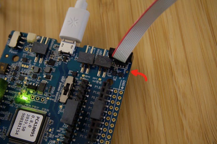
If you still plan on using the onboard chip, then don’t short this jumper! Considering i’m using mine only as a programmer, so I bridged this jumper. (the picture above was before I jumped it with my trusty soldering iron)
After hooking things up, It’s time to do a quick smoke test. Running nrfjprog -r in a terminal should show this result:
$ nrfjprog -r
Applying system reset.
Run.
Success!
I’ve been using Nordic stuff for a while so I already had nrfjprog installed. More info about nrfjprog and other Nordic Command Line tools is here.
Setting up the environment
To get started, Nordic has documentation located here. I’m on OSX so Nordic recommends to use the “Getting Started Assistant” in nRF Connect for Desktop.
The advantage of the Getting Started Assistant is that it’s more interactive. You’ll likely need it since there are a ton of 3rd party tools to install. So the original Nordic SDK still wins in that department for sure!
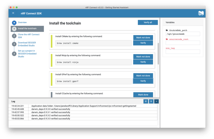
Slowly making my way through the steps..

Most of it is painless. In many cases if you’re an active firmware dev you’ll have these tools installed already.
Installing the IDE (Don’t hurt your eyes)
As a getting started step, Nordic states that Segger Embedded Studio is “required”. I’m not a big fan of these types of IDEs. It locks you into yet another development environment you need to learn etc. I’m big on Visual Studio Code and use it for all the coding I do whether it’s C/C++/Rust/Go/Javascript etc.
You can download from the link they provide in the Getting Started Assistant:

Once downloaded, you can unzip and then copy arm_segger_embedded_studio_v452_macos_x64_nordic (or similar) to your Applications folder. (Or wherever you want!)
Then navigate to it and and run SEGGER Embedded Studio for Arm. The instructions have some more info about how to handle the warning below. As long as you follow the instructions you’ll be golden!

After navigating the interface though, all I wanted to do was barf on my keyboard. The interface is atrocious. (Sorry Segger/Arm!) I’ll be focusing on using Visual Code and the command line for the rest of this tutorial. Nordic only supports Segger so don’t expect any help if you go outside the box!
Working with Visual Studio Code
First of all, there is a way to build SDK examples using the command line. I almost always have a terminal window open and ready for most projects. So this was not new!
The jist of it is the following:
From your ncs directory (you set up earlier of course!), change to the example you want to run.
cd zephyr/samples/basic/blinky
Then run the build using west. west is like a wrapper for a wrapper for a wrapper. It makes building code for Zephyr easy. Despite being another tool that will invariably break, i’m finding it’s makes things simple.
In this case i’m compiling for the nRF9160 Development Kit using the nrf9160dk_nrf9160board definition. (i.e. generating binaries specifically for the nRF9160 DK)
west build -b nrf9160dk_nrf9160
If you get an error about your Python version, make sure your path is set correctly. I had to update my .bash_profile with these lines:
# Zephyr related
export ZEPHYR_TOOLCHAIN_VARIANT=gnuarmemb
export GNUARMEMB_TOOLCHAIN_PATH="~/gcc-arm-none-eabi-8-2019-q3-update"

# Python related
export PATH="/usr/local/opt/python/libexec/bin:$PATH"
Note: if you’re on OSX Catalina you’ll have to set up your .zshrc and .zprofile instead. Remember to open a new terminal window once you’ve done this!
This was nice and all but I didn’t want to compile for the development kit. I wanted to compile for my board! Fortunately there was some documentation on porting over a custom board.
Side note: once 100% tested, i’ll put in a pull request to the Zephyr repo for the board files. That way everyone can use the board immediately with examples!
So let’s get an LED working!
cd ncs/zephyr/samples/basic/blinky
west build -b circuitdojo_feather_nrf9160 --pristine
The --pristine argument will run a clean on all the appropriate files. Otherwise it assumes you’re working with the configuration as before. Subsequent calls you only need to run west build
Side note: the board definition for the nRF9160 Feather will be called circuitdojo_feather_nrf9160. I’ve changed it here as I was testing the board itself rather than the dev kit. 😎
Flashing to a board is as simple as running west flash. You can also run west flash --eraseif you want to erase the full contents of flash. Running either command will rebuild the code if there are any changes.
💡Remember:west flash utilizes the debugger that’s attached to your computer and your board. Without a nRF DK attached to your board you won’t be able to program. If your board has a serial enabled bootloader, you’ll be able to use the built in USB port on the nRF9160. More on that in a sec!
After running you may notice that … nothing is happening! That’s because the processor is still being held in reset. Running nrfjprog -r will fix this and begin code execution. (This requires you have nrfjprog installed. Info on that here.)
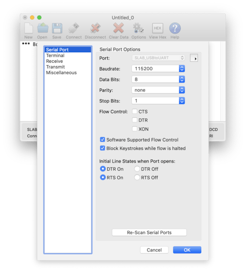
The nRF9160 Feather also comes with a USB to Serial chip by Silicon Labs. On OSX it shows up as SLAB_USBtoUART. (You may need to install drivers for your operating system.)
Here’s an example of what it looks like using Cool Term.
After running nrfjprog -r i also checked to make sure that there was UART output.

Success a blinking LED and a boot message coming over UART to the Silicon Labs chip!
Using the bootloader
One of the more important aspects of any embedded development process is streamlining the uploading of new code to devices. Zephyr makes this easy with MCUboot.
You can find a very basic version of an example with a bootloader within the bootloader repo. First navigate to ncs/bootloader/mcuboot/samples/zephyr/hello-world. Then run the following commands:
west build -b circuitdojo_feather_nrf9160 --pristine
west flash
nrfjprog -r
If you want to compile for another board make sure you change circuitdojo_feather_nrf9160to your board variant name.
Once flashed, here’s the output from CoolTerm:

Nice! Remember your programmer is still connected for this step. Without it you won’t be able to program. That will change momentarily though…
One file that is critical to your Zephyr based projects is prj.conf It’s very similar to the idea of sdk_config.h but much nicer on the eyes. It’s also very similar to how FreeRTS does their configuration as well.
# Print a banner on the UART on startup.
CONFIG_BOOT_BANNER=y

# Enable console and printk()
CONFIG_PRINTK=y
CONFIG_STDOUT_CONSOLE=y

# Enable Zephyr application to be booted by MCUboot
CONFIG_BOOTLOADER_MCUBOOT=y
The most important line is the one with CONFIG_BOOTLOADER_MCUBOOT. This enables the bootloader and shifts your code around automagically. There’s no need to modify linker files. No need to dig into the code and figure out what address has what. All I can say is that it’s very convent!
Testing out loading over USB
Next step is actually getting the bootloader to accept updates from USB. This part, conveniently, is built into the board definitions. So you never have to worry about it.
In the ncs/bootloader/mcuboot/boot/zephyr/boards folder, I created a new file specific to the nRF9160 Feather. Inside I add a few definitions that will enable loading via USB-to-Serial. You will not have to set these yourself.
# Disable Zephyr console
CONFIG_CONSOLE=n
CONFIG_CONSOLE_HANDLER=n
CONFIG_UART_CONSOLE=n

# MCUBoot settings
CONFIG_BOOT_MAX_IMG_SECTORS=256

# MCUboot serial recovery
CONFIG_MCUBOOT_SERIAL=y
CONFIG_BOOT_SERIAL_DETECT_PORT="GPIO_0"
CONFIG_BOOT_SERIAL_DETECT_PIN=12
CONFIG_BOOT_SERIAL_DETECT_PIN_VAL=0
If you do a west build back in the example directory, you’re code will update to add that feature. (Again, i’m impressed!) Then use west flash to flash your bootloader + application combo to your device.
I was a little confused where to go here so this took a while to reach. I eventually stumbled on this post on Devzone which outlined what needed to be done. Nordic also wrote up a tutorial on how to update the Thingy91 over USB. That post is here.
The most important thing I got out of those posts? Turns out we need one more utility to make everything happen: mcumgr
To install you’ll need Go version 1.7 or greater. If you don’t have it installed, run brew install go. For other platforms you’l have to install according to the information here.
Now, run go getgithub.com/apache/mynewt-mcumgr-cli/mcumgr from any terminal. This will install and allow you to run mcumgr which will do the transferring for us!
Ok, so now we have a bootloader + app on the board. Now what?
We need to put the board into DFU mode.
In the MCUboot serial recovery section of the configuration file, we can also define a pin to enable DFU mode on a cold start. So in order to make DFU mode go you can hold the MODE button and tap the reset button on the nRF9160. DFU mode is nearly instant and can accept an update within a second or two.
(Ideally in the future you won’t have to do this, but for now this is the workflow!)
As your remember from before we loaded up first with a “Hello World” type message. Now, I mashed together the Blinky example with that one. See the transformation below:
/* * Copyright (c) 2017 Linaro, Ltd. * * SPDX-License-Identifier: Apache-2.0 */

#include <zephyr.h>
#include <sys/printk.h>

void main(void)
{
	printk("Hello World from %s on %s!\n",
	       MCUBOOT_HELLO_WORLD_FROM, CONFIG_BOARD);
}
To:
/* * Copyright (c) 2017 Linaro, Ltd. * * SPDX-License-Identifier: Apache-2.0 */

#include <zephyr.h>
#include <sys/printk.h>

#include <zephyr.h>
#include <device.h>
#include <devicetree.h>
#include <drivers/gpio.h>

/* 1000 msec = 1 sec */
#define SLEEP_TIME_MS 1000

/* The devicetree node identifier for the "led0" alias. */
#define LED0_NODE DT_ALIAS(led0)

#if DT_HAS_NODE(LED0_NODE)
#define LED0 DT_GPIO_LABEL(LED0_NODE, gpios)
#define PIN DT_GPIO_PIN(LED0_NODE, gpios)
#if DT_PHA_HAS_CELL(LED0_NODE, gpios, flags)
#define FLAGS DT_GPIO_FLAGS(LED0_NODE, gpios)
#endif
#else
/* A build error here means your board isn't set up to blink an LED. */
#error "Unsupported board: led0 devicetree alias is not defined"
#define LED0 ""
#define PIN 0
#endif

#ifndef FLAGS
#define FLAGS 0
#endif

void main(void)
{
	printk("Hello World from %s on %s!\n",
				 MCUBOOT_HELLO_WORLD_FROM, CONFIG_BOARD);

	struct device *dev;
	bool led_is_on = true;
	int ret;

	dev = device_get_binding(LED0);
	if (dev == NULL)
	{
		return;
	}

	ret = gpio_pin_configure(dev, PIN, GPIO_OUTPUT_ACTIVE | FLAGS);
	if (ret < 0)
	{
		return;
	}

	while (1)
	{
		gpio_pin_set(dev, PIN, (int)led_is_on);
		led_is_on = !led_is_on;
		k_msleep(SLEEP_TIME_MS);
	}
}
(I’m combining the Zephyr blinky example with the MCUboot hello-worldexample.)
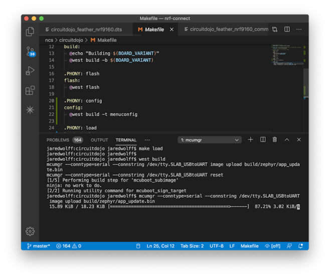
Then to update over serial you can run mcumgr with similar arguments.
west build
mcumgr --conntype=serial --connstring /dev/tty.SLAB_USBtoUART image upload build/zephyr/app_update.bin
mcumgr --conntype=serial --connstring /dev/tty.SLAB_USBtoUART reset
Remember to replace /dev/tty.SLAB_USBtoUART with your serial port. build/zephyr/app_update.bin should stay the same.
Shortly after I got a blinking LED and a Hello World message over serial (after I reconnected using Cool Term). Now we’re cooking with gas!
Testing Peripherals
One thing I like to do is make sure that all peripherals are working as expected. Some things can be tested without firmware (like the charger). Some require some firmware intervention. For example, setting up I2C + the RTC looks something like this in Zephyr:
/*
	 * Set up I2C
	 */
	struct device *i2c_dev;
	i2c_dev = device_get_binding("I2C_2");
	if (!i2c_dev)
	{
		printk("I2C: Device driver not found.\n");
		return;
	}

	// Configuration
	u32_t i2c_cfg = I2C_SPEED_SET(I2C_SPEED_STANDARD) | I2C_MODE_MASTER;
	if (i2c_configure(i2c_dev, i2c_cfg))
	{
		printk("I2C: config failed\n");
		return;
	}

	// Write a test command and check for ACK
	uint8_t buf[] = {0};
	ret = i2c_write(i2c_dev, buf, sizeof(buf), PCF8506_I2C_ADDR);

	if (ret < 0)
	{
		printk("I2C: Unable to communicate with RTC.\n");
		return;
	}
In order to use I2C, make sure that this is in your prj.conf:
CONFIG_I2C=y
CONFIG_I2C_2=y
The nRF9160 uses “I2C2” peripheral as this is default for the development kit. You should keep this the same for now.
I ran another west build and loaded the app over using mcumgr.
Hooking up my Saleae, I got a nice result after loading and resetting the device:
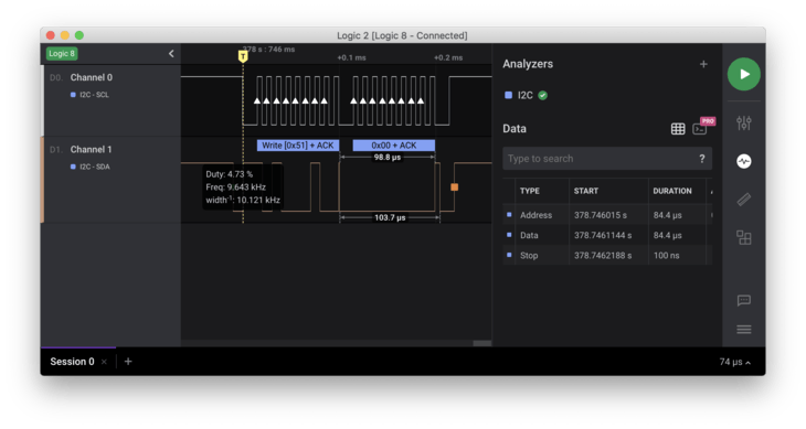
For some reason 0 byte transfers don’t work. But that’s ok. Sending some dummy data works just as well!
Next steps!
I have an ever growing list of bringup tests I want to run before making the nRF9160 official. I’m taking no shortcuts here to make sure these boards are a stable foundation you can base your own designs on.

I’m also working on something special related to LTE which will make it much easier for you to get started with nRF9160. More on firmware, hardware and more in coming posts. Make sure you’re subscribed to the list to stay up to date on progress.
Until next time!
Discussions
Become a Hackaday.io Member
Create an account to leave a comment. Already have an account? Log In.