TWS Earphone Charging Case by JLCPCB
Introduction: TWS Earphone Charging Case by JLCPCB

JLCPCB Solution for TWS Earphone Charging Case
Step 1: Basic Function
A. charge the case with 5V power supply
B. Wireless charging can be used to charge the charging box
C. The headset and charging box can be charged simultaneously
D. it can be charged separately for the earphone, and the earphone can be disconnected automatically
Step 2: Details
A. Case Battery: 3.7v /400mAH, with lithium battery protection IC
B. Earphone battery: single ear 3.7v /55mAH, PCB with protection board
C. Three indicator lights for electric quantity in the charging box (to indicate electric quantity)
D. type-c charging interface for charging box, and PIN contact TYPE for earphone charging interface
E. Charging case with OVP
F. Put the earphone into the charging box. The earphone will be automatically charged until it is fully charged
G. Charging of left and right ears are in separate type (to avoid the power of the left and right ears being out of sync after being used alone) H. Over-voltage detection at the wireless end (overcharge protection)
Step 3: Step 3:Solution Scheme

a、Type-C Interface
Type C is used for the interface, or Micro USB can be selected as the entrance of external dc power supply, and TVs can be connected to VBUS for electrostatic protection
Step 4 : MCU

MCU is the master control, control the switching logic of power charging and wireless charging, indicator light display, control sleep, etc.
Recommended: MCU C18615
ST STM8S003F3P6
Step 5: Charge IC

Charge IC C84051 FM TC4056A SOP8
OVP IC C401024 Arrow AW33905FCR
Get them from LCSC
Step 6: Booster IC
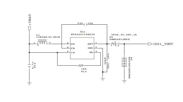
The booster IC, we use Shanghai Yutai's ETA1061, and the battery voltage rises to 5V to charge the headset directly.ETA1061 is fully integrated into the upper and lower power tubes, which can realize a synchronous voltage boost of a single chip. It can be fixed 5.0v output or through a large external resistance to achieve voltage adjustment from Vin~ 5.0v, the periphery is very simple.
Step 7: Wireless Charging and Receiving Module

The wireless charging and receiving module comes from COPO CP2031 in Nanjing, which meets the WPC Qi standard protocol (2016.12 has passed the WPC Qi certification), the single-chip solution with the maximum output power of 5W (5V / 1A), the system charging efficiency of > 70%, and it is compatible with external AC Adapter or USB input and supports intelligent switching.
The whole solution can be manufactured in JLCPCB
 ROFLhoff
 Open Green Energy
 Enki
Enki
 isaacporras