The line of distinction between microcontroller and computer continues to blur. Although our mind and language struggles to define what is and isn't a computer, the definition must be left for the dictionary. No matter the word used, the main objective shall be to understand: Does this direction of progress actually simplify and accelerate development?
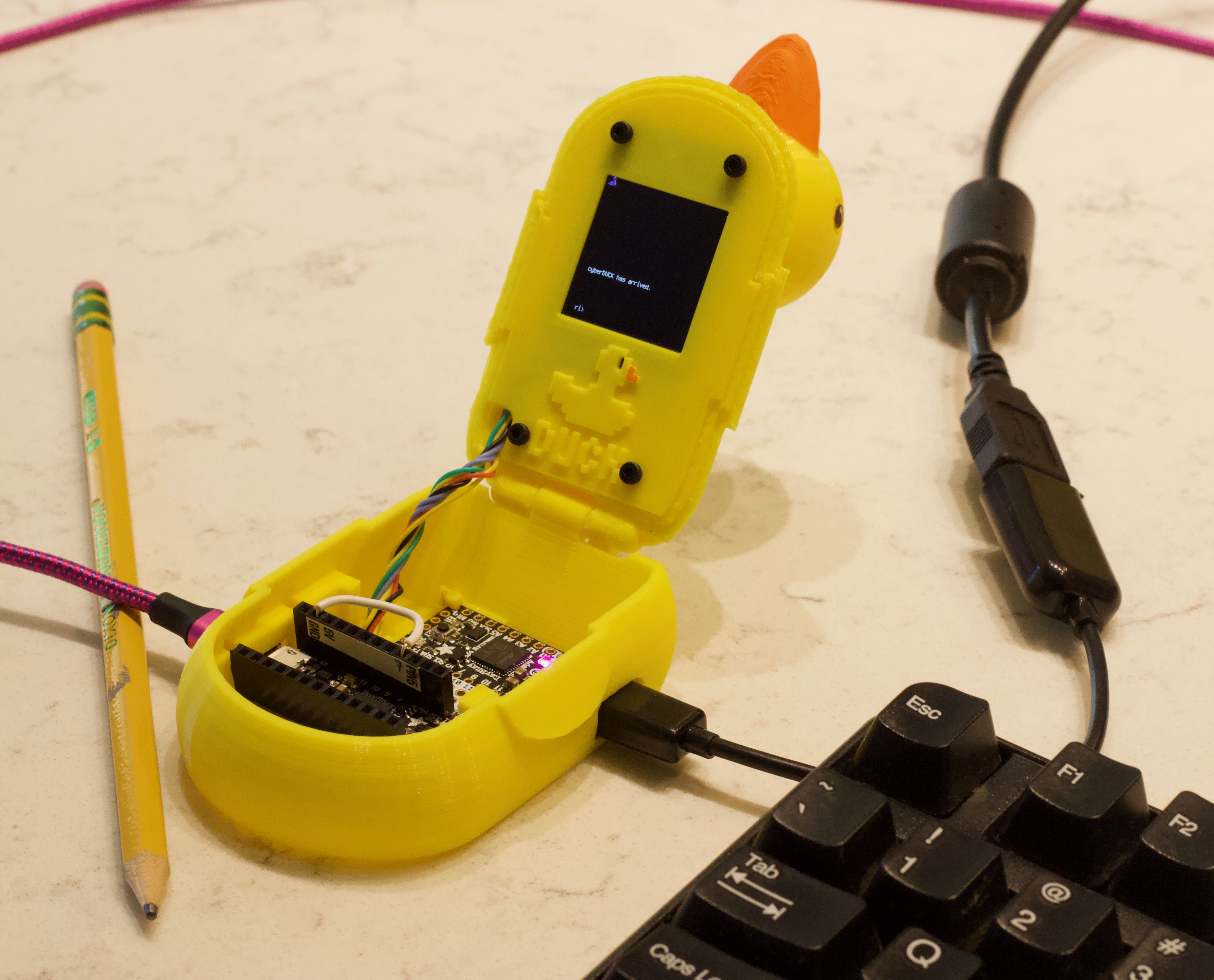
cyberDÛCK: A baby, waddling step toward flexible, low-cost, fully self-contained portable prototyping rig that you can program on the fly!
Key features:
USB Keyboard input (now handles long key presses)
Display for showing output
A text editor for creating and editing python code
A "REPL"-like command line for entering python commands (to edit file, run file, etc.)
Duck-shaped
Primary Outcome: Demonstrate a computer using CircuitPython
Secondary Outcome: Show what is possible so that new features might get integrated into simpler hardware designs and software hooks (e.g. Bluetooth Low Energy keyboard input)
Who is this for: Anyone that wants a self-contained, portable, prototyping computer running CircuitPython that’s in the form of a hinged duck
Use cases: This could be useful as a part of ultraportable microcontroller electronics prototyping kit
Strategy
As a prototype, the objective of this project is to hack together something that can demonstrate the concept. It is deliberately taking bits and pieces from others and using glue, Fun-Tak, feathers and bailing wire to make it work.
Use a co-processor to take input from a USB keyboard (Arduino-based USB Host for SAMD with software modified from code by gdsports)
Transmit keyboard input to main processor using UART
Use a "REPL-interceptor" to allow text input from UART to control the command execution of python input from the keyboard
Adapt a text editor MicroPython-editor (pye) from robert-hh to run on a CircuitPython Board with attached display. This will edit files by taking input from UART and output to the attached display. File storage is using on-board non-volatile memory or a memory card
Project outline
Background
Objectives/Strategy: A stand-alone programmable on the fly CircuitPython entity and the conceptual chucks of stuff needed to get there
USB Host controller: Keyboard to UART input controller (run with Arduino) with a hack for handling directional arrow keys; uses USB on-the-go (OTG) cable
REPL-interceptor: this takes input from UART to run (exec) python text commands
Bill of Materials and Mechanical design: duck-shape, of course
Next steps
The original Inspiration: the things that are major steps toward this goal, and some fun stuff
Background
The advent of MicroPython and CircuitPython has streamlined quick prototyping of microcontrollers. However, to date the programming of microcontrollers has been tethered to a computer. In the case of Arduino programming, we require a compiler to create, compile and download the code. CircuitPython along with the extremely helpful mu editor has now eliminated the "compile" step of the process, by downloading the .py file directly onto the microcontroller as if it were a USB memory stick. Also, inclusion of the python REPL speeds up debugging of the python code.
All of these advancements combined have streamlined and simplified the process from idea conception to hardware demonstration.
However, the "computer" tether remains. Currently the stdout print() statements are mirrored to a serial connection that is displayed on the computer. As of about CircuitPython version 4, the stdout and REPL display can now be directed to a connected display. This is yet another advancement toward a full "computer" using CircuitPython. The final remaining barrier is to provide software input to the microcontroller without a computer. Here are the steps I followed to make this CircuitPython computer duck:
USB Host Controller
To receive inputs from a keyboard, we need to use a USB Host controller. This USB Host controller accepts keyboard inputs, processes them and then communicates them to another board using the UART.
To do this, we need a board setup to put it into this USB Host mode, in my case I use an Arduino program running on an Adafruit ItsyBitsy M4. The software is included in the files. I got inspiration from gdsports library, but ended up using a way simple version.
One key feature of this KeyboardController.ino code is that it capture several special keys (directional arrow keys up down left right, and a couple of other special keys). Since these special keys do not have ASCII codes, they are handled specially. Since we will be doing text editing, the arrow keys are mandatory to make the experience a good one. Also, I've included a few lines of code that provides repetitive keypresses for when you hold down a key, with a couple of tunable delays for your preference.
A couple of special things to know.
1. You will need a special USB adapter to convert from the keyboard USB plug to the microcontroller Micro USB plug. This is often called a USB On The Go (OTG) cable. 2. Once the board is programmed for USB Host mode, you will no longer be able to be get any outputs from the board onto the serial console for debugging purpose. (Maybe some one will find a way, but I couldn’t.) One way to add debugging capability is to build this USB Host controller with a display, so you can write print statements to connected screen.
So, load the KeyboardController Arduino sketch onto your USB host controller board and hook up your keyboard through the USB on the go cable. Now we need something to collect the UART data from the USB Host controller and do something useful with it.
REPL-interceptor: use UART inputs to run commands
The python REPL (read evaluate print loop) is a useful tool allowing you to type in commands and see what happens. It allows you to debug code and try things quickly, right on the hardware. CircuitPython now has a REPL that communicates over the USB serial terminal. Also, the output is mirrored on the serial console and also any displays that are connected and setup properly. Input for the REPL is via input from the serial terminal, this can be using the built-in terminal of the mu editor, or by a terminal window on your PC (sometimes putty or terminal is used).
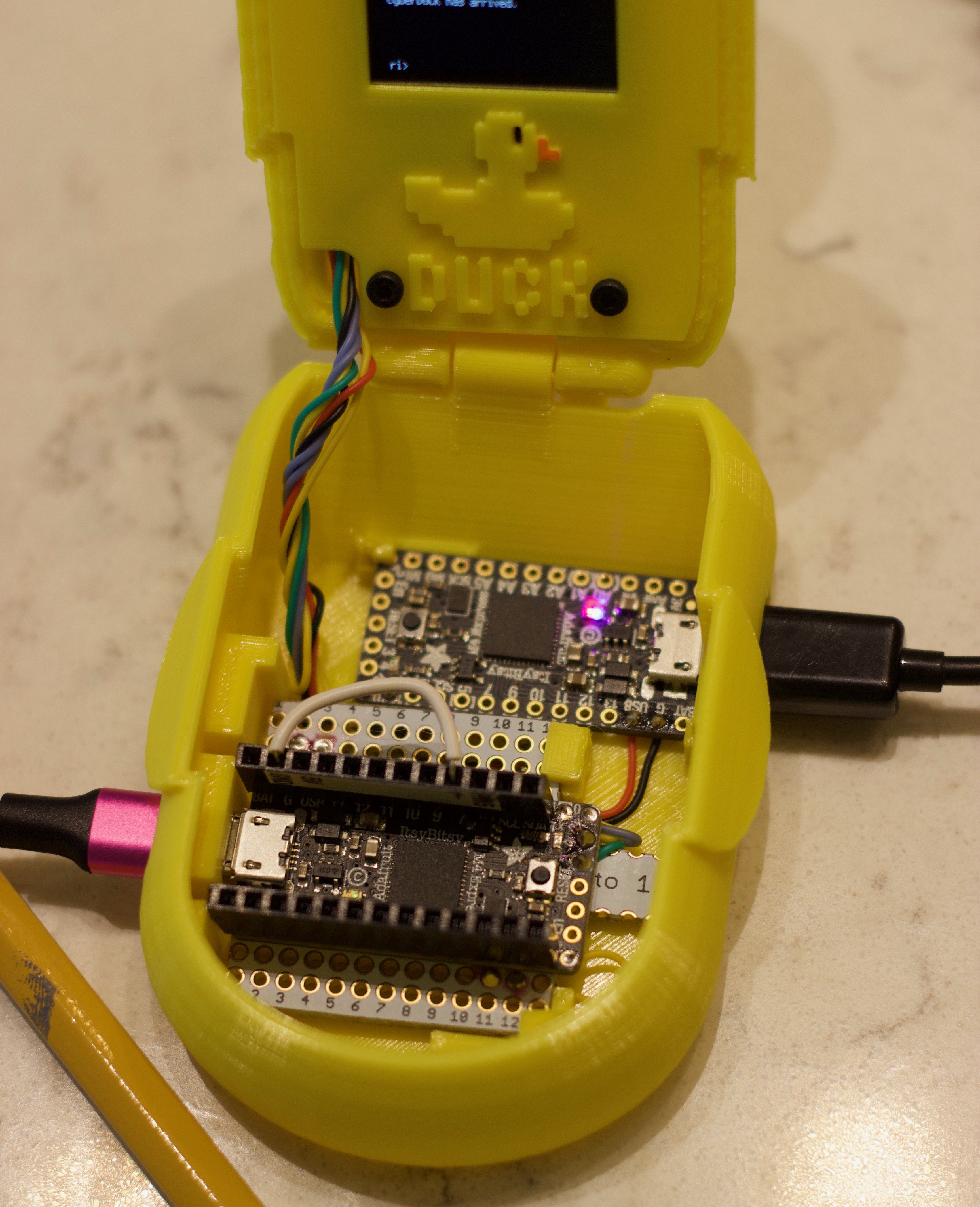
Since we have an external keyboard and this USB Host controller outputting to the UART, we need our main controller board to accept text input via UART and then run those commands. So, I’ve created a wrapper that I call REPL-interceptor. It “intercepts” text input from the UART and runs those commands. Also, it spits all “print” statement output to both the serial console and a connected display. For my setup, I use a second Adafruit ItsyBitsy M4 connected via SPI to a 1.3” TFT display 240x240 pixels. This is connected to the USB Host controller through the UART RX and TX connections. (Remember, connect RX on board A to TX on board B and TX on board A to RX on board B.)
The REPL-interceptor (ri) collects text lines and when you press enter it runs these commands using the
exec
command. Not much else to see here, when do we get to the duck part, anyway?
Text Editor
SUPER CAUTION DANGER NOTE: At your own risk, use this editor. It is rickety-hacky right now so don't trust it with anything important. You've been warned. Save early and often.
Wanna edit text directly on a CircuitPython board? Are you crazy? Of course you can!
Wow, we can actually do this. There were a couple of big hurdles that were already overcome. When you break it into chunks you can debug each and then not get overwhelmed by everything at once. But now here’s a big one where diligent folks have lead the way: the editor. We want to write code and run it all on this standalone cyberDÛCK right so we need something to type, edit and save text files. Luckily the path was laid by pfalcon’s pyedit and robert-hh’s MicroPython editor. The MicroPython editor was setup for input and output on the serial console using VT100 commands. This needed additions of taking UART inputs (adding it back in from a previous revision) and Including output to a display.
Starting with robert-hh’s code, I added back in the UART input and this worked fine. IMPORTANT: If you have trouble with some key codes not working right, please check in two places, including your USB Host controller and also the pye_mp.py file also has some key mappings near the top,of the file. To debug issues I added a bunch of print statements Into the python “rd” function so that I could read the integer and ASCII decoded inputs from the UART. This helped me figure out how to Deal with tricky keys, such as the arrow keys.
Now, we need to deal with displaying the editor in the connected SPI display. Ideally there would be a terminal that can decode all the VT100 commands. I couldn’t find one so I made a hybrid “simple terminal” that is suitable for this editor. This simple terminal class allows you to setup a text box of a given size and location, and keep track of the insertion point. I call this class is a hybrid Terminal since it doesn’t deal with all the VT100 commands, but it gets the job done. For this editor, I actually make two terminals, one for the main text and a single line terminal for the status line. The reason for this is because the status line should be highlighted. It was easiest to do this with two terminals, but with a different palette for the highlighted status line. Correction, I actually used three terminals, the third is a single character terminal to handle the cursor. My python simpleTerminal class file and the updated editor file are in the project file storage or on GitHub. A couple of important notes:
1. See the note about key mapping above.
2. You can switch input between UART and standard serial console input by changing the Boolean “inputUART”.
3. You can change the output to the serial console by Modifying the “displayOutput” Boolean.
4. Check your SPI settings are correct for your wiring. My display does not have a chip select pin. My generic SPI display runs on SPI_MODE 3. Yours probably doesn’t, so update the SPI polarity and phase settings to meet your needs.
Here is the editor in action, editing the first program written and executed directly on my initial hardware setup, ‘cyberduck.py’. Here is the output of this first program:
USB power supply and USB cable to power the main controller (mine is pink)
240x240 pixel 1.3” TFT display run via SPI. I bought a generic unbranded version on eBay. IMPORTANT: This display model uses SPI_MODE3. Your display probably runs using SPI_MODE1. Check what SPI settings your display uses and then update the code to set the polarity and phase correctly for your display’s SPI_MODE.
Piece of proto board, used for the main controller connections
Headers, 2 quantity
Some ultraflexible silicone insulated wires
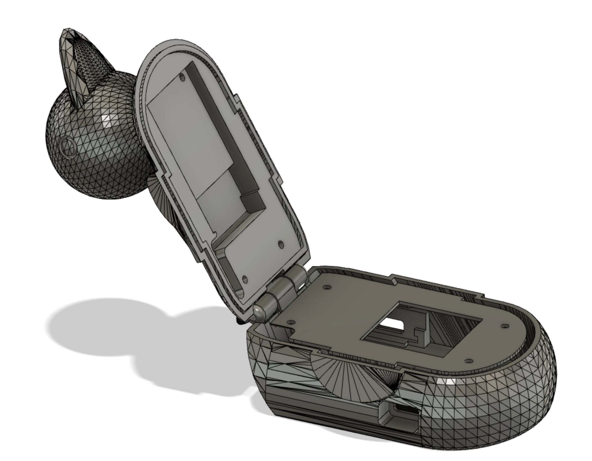
cyberDÛCK (3D printed): top, base, bezel and a piece of filament for the hinge pin). Thanks to my love, Mgt for the duck model!
M2 x 6mm bolts: 4 quantity
Wiring
USB Host (ItsyBitsy M4)
Main Controller (ItsyBitsy M4)
SPI TFT display
GND
GND
GND
USB (+5V)
USB (+5V)
VCC
TX
RX
RX
TX
SCK
SCL
MO
SDA
D3
RES
D2
DC
D4
BLK (backlight)
D7 (connect to +5V "USB" or GND) see important note below about writing to the file system
IMPORTANT: The way that CircuitPython current works, the filesystem can only be written by either the USB or by the local microcontroller. You can modify the boot.py file so that on a HARD boot, it will check one of the pins and decide who has write access. During uploading code files, set the USB to have write access. When you want to edit text files directly on the cyberDÛCK, change the pin to get write access and do a hard reboot.
To achieve this you need to change the boot.py to check a pin and decide whether USB or the chip has control over writing to the filesystem. (I am including the boot.py file that I use.) It checks pin D7 and if it is connected to +5V, then you can write files over USB. If D7 is connected to GND, then the microcontroller can write to the filesystem. So hook up a wire or a switch to D7 so it will either connect to +5V (USB) or GND. You can see my white wire in the close-up picture of the circuit board. It's connecting pin D7 to GND, thus my editor can write files. Yay!
SUPER IMPORTANT: Don't get too creative messing with the boot.py file, or else you could lock yourself out from writing files to the board. Then you would have to clear everything off the board and start again. If you mess up really bad, at least you can download your files and save them somewhere, you just won't be able to write anything from USB.
cyberDÛCK design: Hinged design was selected for maximum portability, water resistance, tilt function visibility and all-around good looks. The 3D modeling was performed in Fusion 360 (file is included), sliced with Cura, and 3D printed on a Creality CR10-S using HatchBOX yellow. The beak and eyes were painted to further evoke emotion and elicit joy. The electronics were fixed position with some small filament blocks with heat used to weld these board keepers into place.
Next Steps
If someone can get their hands on these parts, now someone needs to do this with a Bluetooth keyboard, maybe with an Adafruit CircuitPlayground Bluefruit with Gizmo or an Adafruit Clue.
Inspiration
Some inspirational examples of earlier progress toward this goal of a standalone computer using CircuitPython:
Bluetooth keyboard connected to a PC computer that then sends commands through a serial terminal via USB to the CircuitPython REPL on an Adafruit pyPortal
Bluetooth connection to Adafruit Clue that sends audio signals to a TTY machine that is translated into text
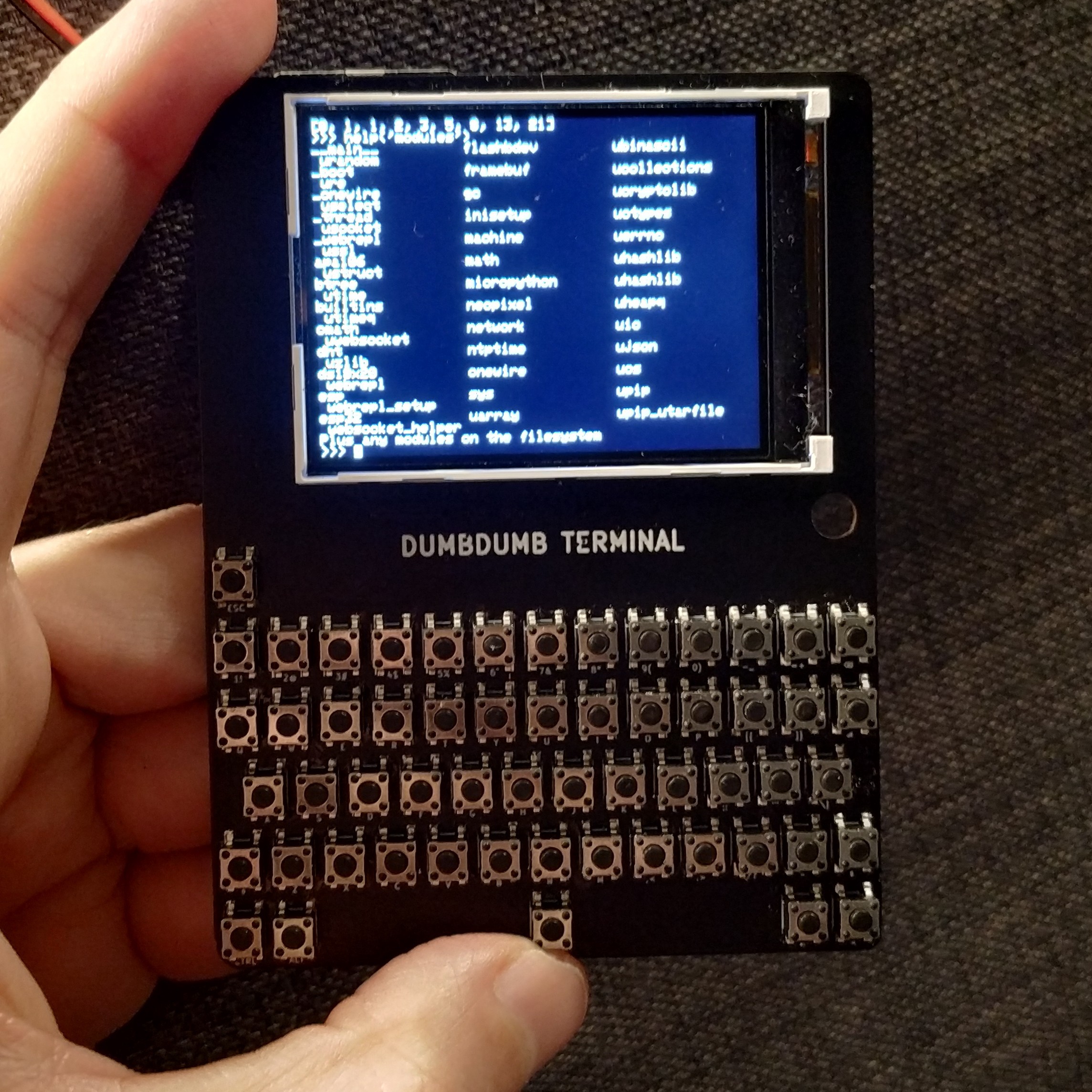
A display and attached keyboard running on a CircuitPython DumbDumb
Slightly “tongue-in-cheek’: A keyboard to a laptop to a Arduino that controls typewriter-like slide and solenoids that sounds like a typewriter along with haptic feedback and personal intervention for carriage return here
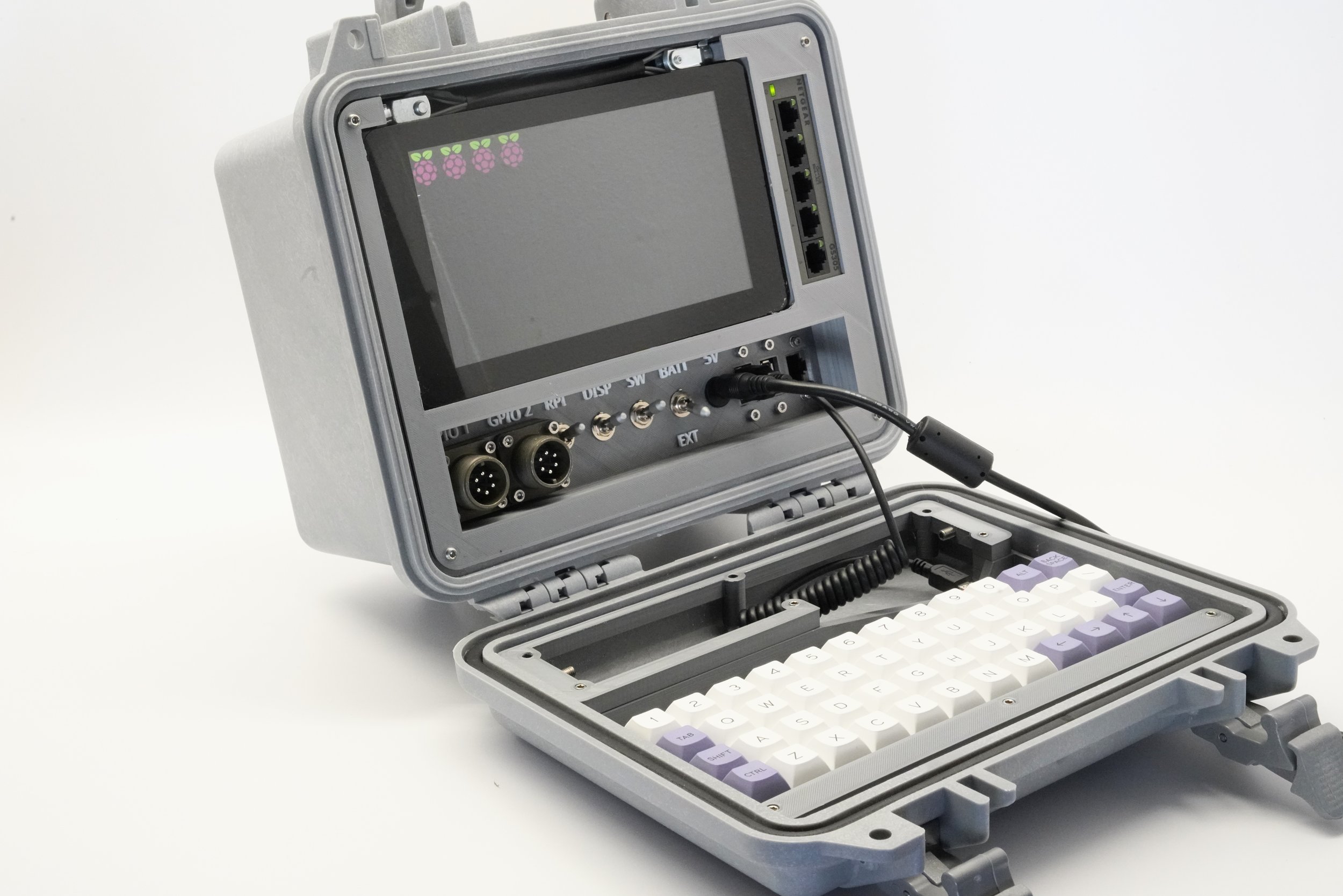
Also there are an increasing number of bold, creative and capable disaster recovery machines being built these are typically luggable, often described as “cyberdeck”. These often use Raspberry Pi such as in this slick example from back7.
Other portable calculating computers include a keyboard and fit easily in a backpack
 kmatch98