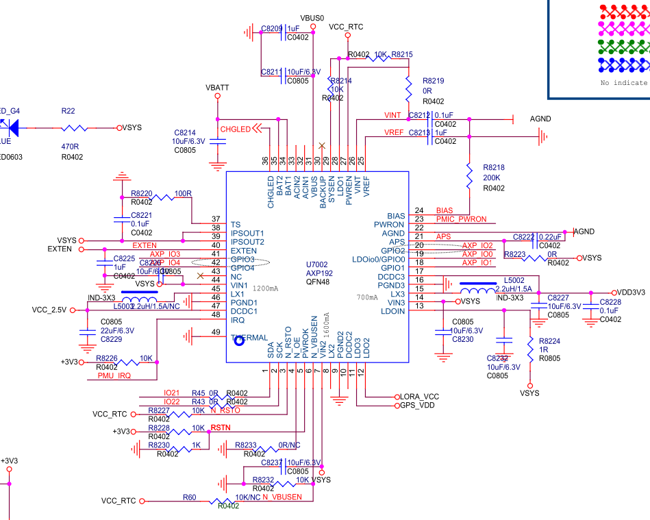
Just the "simple" task of turning on the T-Beam is perhaps a little more complicated than what I'm used to from a microcontroller board. It includes a fully blown Power Management Integrated Circuit (PMIC) chip, which has 3 LDO linear regulators and 3 DC-DC buck converters, controllable over i2c.
The chip is an X-Power AXP192, which unfortunately I can't find a full English datasheet for, however I have found enough resources to get by. This is the same PMIC used in the m5stack modules, so there is a fair amount around.
The things I've been using are:
- A "brief" English datasheet, which lacks any detail: http://www.x-powers.com/en.php/Info/down1/id/29
- A full Chinese datasheet, which is pretty readable with the help of Google Translate: https://github.com/m5stack/M5-Schematic/blob/master/Core/AXP192%20Datasheet%20v1.13_cn.pdf
- A GitHub repo with some documentation which seems to be cherry-picked translations of the datasheet: https://github.com/ContextQuickie/TTGO-T-Beam/wiki/AXP192-Information
- An Arduino library: https://github.com/m5stack/M5StickC/blob/master/src/AXP192.cpp
- A "hardware agnostic" library, in C rather than Arduino: https://github.com/tuupola/axp192
Alongside the PMIC itself, we need to know how its voltage rails are wired in to the components on the board. Annoyingly, the first hit on Google seems to go to the wrong GitHub repo. This one appears to have the correct schematic and example code: https://github.com/Xinyuan-LilyGO/LilyGO-T-Beam

The board seems to have been designed with a few different options in mind, with various components not populated. It's not entirely clear from the schematic what is to be expected from the board, so I spent some time checking out the various circuits.
On my board, things are wired like so:
| Power Rail | Voltage | Net name + Components |
|---|---|---|
| LDO1 | 2.5 V fixed (it seems like maybe this is different for different versions of the AXP192, but I can't find any information on that) | VCC_RTC Only powers GPS backup battery |
| LDO2 | 1.8 - 3.3 V variable | LORA_VCC Powers the LoRa module |
| LDO3 | 1.8 - 3.3 V variable | GPS_VDD Powers the GPS module (2.5 - 3.6 V) |
| DCDC1 | 0.7 - 3.5 V variable | VCC_2.5V Despite the name, this powers the 3.3V pads on the header pins |
| DCDC2 | 0.7 - 2.275 V variable | Not Connected |
| DCDC3 | 0.7 - 3.5 V variable | +3V3 Powers the ESP32, is on by default at powerup. Annoyingly, this also feeds the ESP32's RTC power supply, so we can't power off the rest of the ESP32 whilst keeping the RTC on. |
In addition to the AXP192, there's a discrete LDO 3.3 V regulator, which just powers the on-board CP2104 USB-to-Serial converter from the USB bus. As far as I can tell, this isn't connected at all when running on battery power, so it shouldn't leech any unnecessary power.
Initial code
I grabbed tuupola's library and the ESP32 IDF and got started. I ran into a few issues with the way tuupola's library uses build system #defines to set register defaults, and it didn't give me the level of control I was hoping for, so I've forked it and will see about merging my changes back when I'm happy with it: https://github.com/usedbytes/axp192
I did run into one slightly embarrassing issue by accidentally disabling DCDC3 as the first thing my code did when the ESP32 boots - that immediately powers of the ESP32, and made it a little tricky to re-flash good code. I had to spam the reset button and hope that the flashing tool managed to get in just before the bootloader jumped to my buggy code. I think there are pins I could use to force the chip to stay in the bootloader if I got really stuck, but I managed to get some good code back on after a couple of attempts.
With my modifications to the library, I could quickly start controlling all the different power rails, and got the GPS powered up and outputting data - so we're off to a good start.
    // Power off everything we don't need
    axp192_set_rail_state(&axp, AXP192_RAIL_DCDC1, false);
    axp192_set_rail_state(&axp, AXP192_RAIL_DCDC2, false);
    axp192_set_rail_state(&axp, AXP192_RAIL_LDO2, false);

    // Set the GPS voltage and power it up
    axp192_set_rail_state(&axp, AXP192_RAIL_LDO3, false);
    axp192_set_rail_millivolts(&axp, AXP192_RAIL_LDO3, 3300);
    axp192_set_rail_state(&axp, AXP192_RAIL_LDO3, true);

    // Set up a UART for the GPS
    uart_config_t uart_config = {
        .baud_rate = 9600,
        .data_bits = UART_DATA_8_BITS,
        .parity    = UART_PARITY_DISABLE,
        .stop_bits = UART_STOP_BITS_1,
        .flow_ctrl = UART_HW_FLOWCTRL_DISABLE,
        .source_clk = UART_SCLK_APB,
    };
    uart_driver_install(UART_NUM_1, BUF_SIZE * 2, 0, 0, NULL, 0);
    uart_param_config(UART_NUM_1, &uart_config);
    uart_set_pin(UART_NUM_1, GPIO_NUM_12, GPIO_NUM_34,
                 UART_PIN_NO_CHANGE, UART_PIN_NO_CHANGE);

    uint8_t *data = (uint8_t *) malloc(BUF_SIZE);

    for ( ; ; ) {
        // Read data from the GPS
        int len = uart_read_bytes(UART_NUM_1, data, BUF_SIZE, 20 / portTICK_RATE_MS);
        // Send the data to the serial console
        fwrite(data, 1, len, stdout);
        fflush(stdout);
        vTaskDelay(500 / portTICK_PERIOD_MS);
    }
After a few seconds of warm-up, I was rewarded with a nice GPS fix! (location redacted...):
$GNGSA,A,3,03,04,11,17,22,,,,,,,,3.40,2.04,2.72*1B
$GNGSA,A,3,71,85,,,,,,,,,,,3.40,2.04,2.72*11
$GPGSV,2,1,07,03,81,244,37,04,26,179,37,11,27,145,34,17,47,293,32*74
$GPGSV,2,2,07,22,70,076,31,36,24,142,32,49,30,174,38*48
$GLGSV,1,1,04,70,56,046,,71,67,210,37,72,16,218,23,85,39,147,29*61
$GNGLL,XXXX.XXXXX,N,XXXXX.XXXXX,E,212332.00,A,A*7A
Next up I want to try the battery charging and monitoring functionality.
Discussions
Become a Hackaday.io Member
Create an account to leave a comment. Already have an account? Log In.
Hello,
I have a LilyGO T-PCIE with a SIM7600E and I use arduino IDE (ESP32 IDF is too complecated for me). Everything is working good. But,
I just need to understand how the AXP192 works. So, I flashed the AXP192.ino from here https://github.com/tanakamasayuki/I2C_AXP192 and I have the same pb like you.
when the ESP32 boots - that immediately powers off the ESP32.
2 questions about that.
1 . When LilyGO T-PCIE is powered up and the ESP32 maintained to reset, the 3.3V is present on the ESP32. Does that mean that some power rail voltage are default defined?
Or some values are they memorized in the AXP132 and the AXP132 can retreive these values at power up?
2 . Can someone help me to debug that library?
I found nothing in the data sheet to explain that.
Thank you.
Are you sure? yes | no