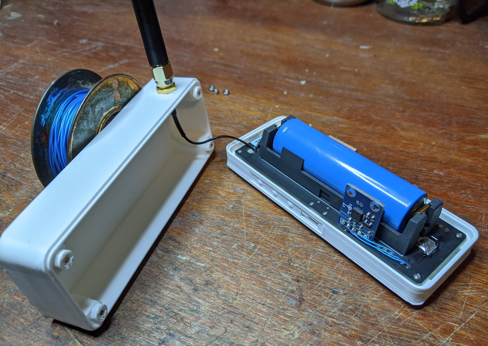
Next up, I've designed a case to keep everything secure and together. There are a few T-Beam cases on Thingiverse already, but they all seem to include the OLED which I don't have, so I jumped into OpenSCAD to design my own.
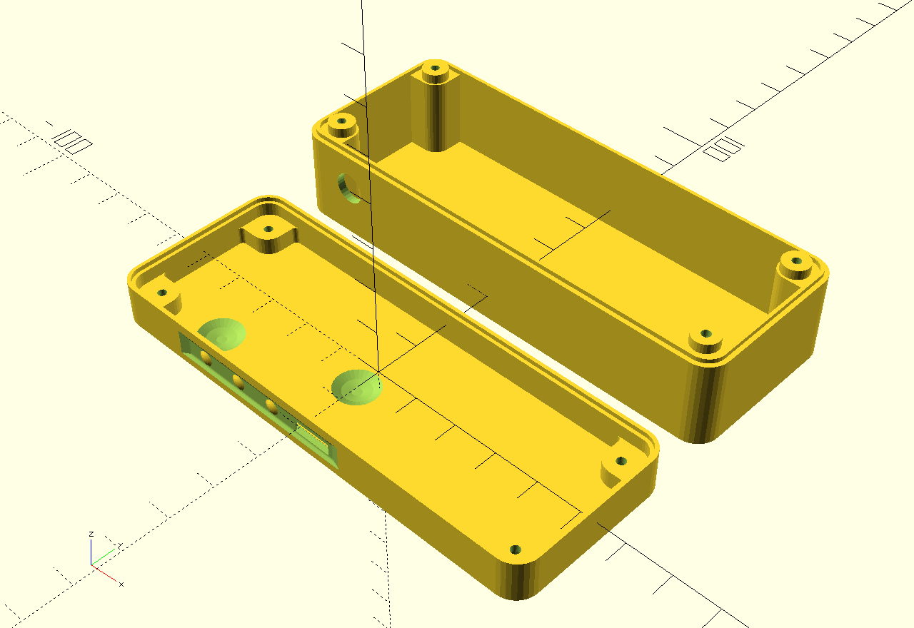
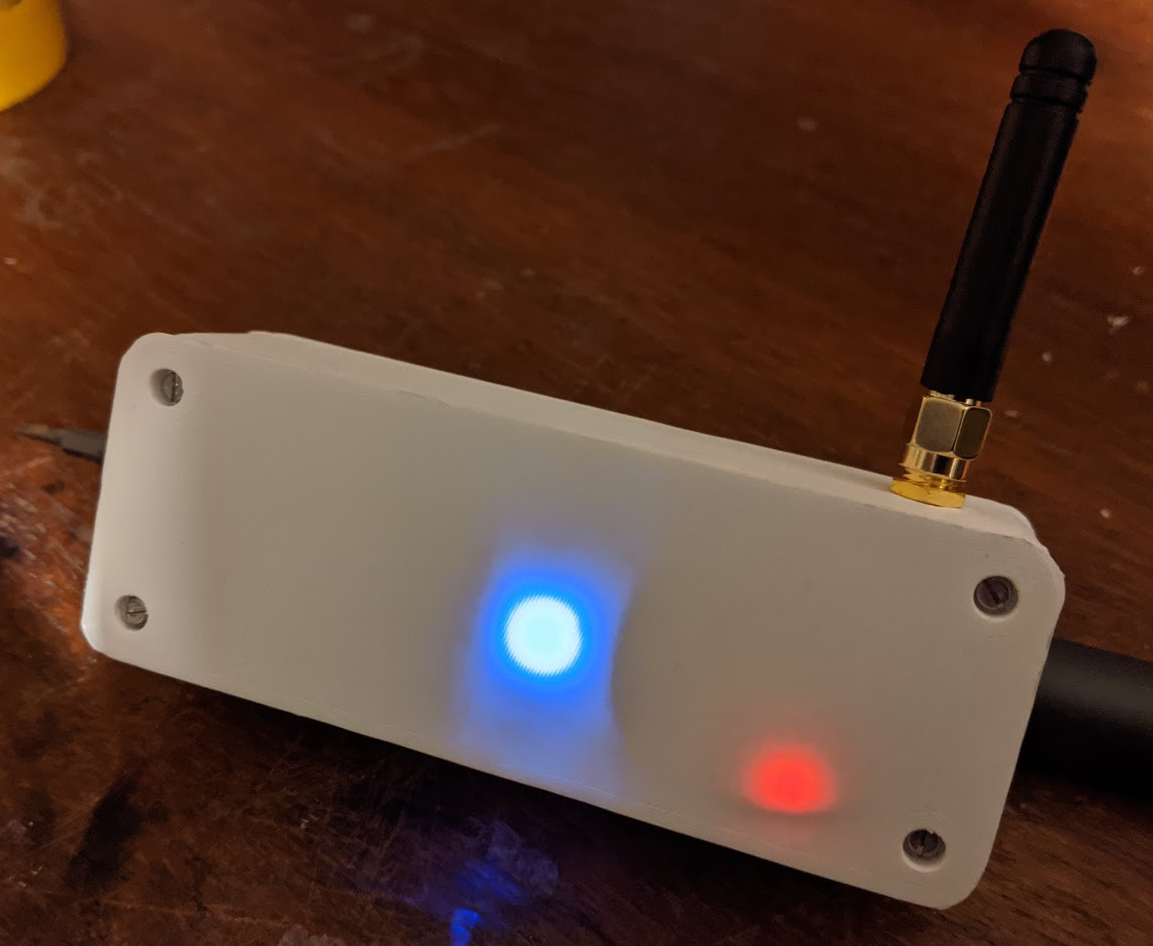
I made the base thin over the two LEDs so that they can shine through (at least somewhat), and also made the wall thin next to the buttons, with little protrusions which are meant to push onto the switch. I made the clearance just a little too large, so it's quite tricky to push the buttons, but it will do for now.
I've pushed the CAD files (and code updates) to my repo on GitHub: https://github.com/usedbytes/tbeam. It's all very messy at the moment while I'm prototyping, but I'll be neatening it up as I move towards the final implementation.
I also soldered in my accelerometer. It uses analogue outputs, which is good for my use-case because I want to monitor it during deep-sleep, and that seems easier to do on analogue pins than having to handle i2c traffic from the ESP32 low-power coprocessor code.
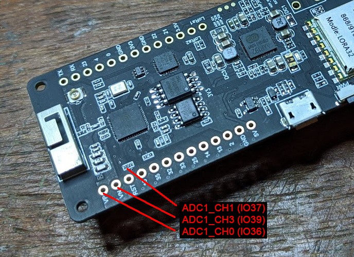
I found the ESP32 documentation around the ADC routing a bit confusing, but did eventually identify three pins which I can access on the T-Beam, and that can be used for ADC1 from the low-power coprocessor.
The T-Beam's RTC + ADC1 GPIOs are pretty well filled up with the board's functionality. I found three pins I could use. Only two of them are broken out to pads on the headers, the third (IO37) is available as a pad on one of the not-populated 0402 components. Annoyingly, IO37 is also wired to the GPS module time pulse output, so I had to remove R41 to disconnect that. I'm not planning to use the time pulse, so this shouldn't really be a problem - but if I do want it I will just wire it to a different pin.
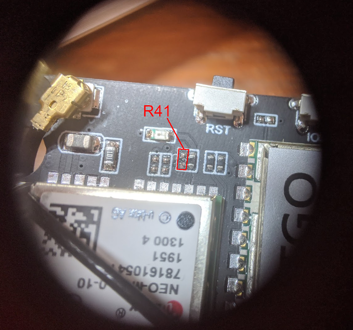
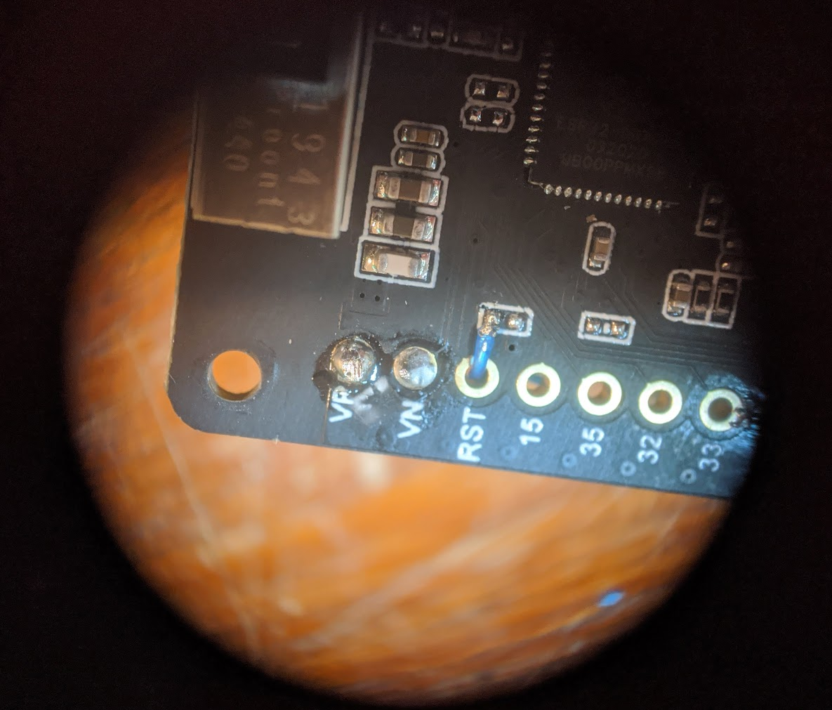
The not-populated pad is R67 in the schematic, and the pad closest to the WiFi antenna is IO37. VN and VP are for the internal hall effect sensor, but I don't plan to use that so I'll use those.
I've wired the accelerometer VCC pin to IO25. It's meant to have a very low active current (400 uA, not that I believe it) - so a single GPIO should easily be able to source enough current, and having it on a GPIO makes it easy to turn on and off. It's probably more efficient than spinning up the unused AXP192 DCDC1 output, too.
Which a tiny bit more code, I can read out the voltage for each axis:
// Power up the accelerometer VCC GPIO
io_conf.intr_type = GPIO_INTR_DISABLE;
io_conf.pin_bit_mask = (1ULL << GPIO_NUM_25);
io_conf.mode = GPIO_MODE_OUTPUT;
io_conf.pull_up_en = GPIO_PULLUP_DISABLE;
io_conf.pull_down_en = GPIO_PULLDOWN_DISABLE;
gpio_config(&io_conf);

gpio_set_drive_capability(GPIO_NUM_25, GPIO_DRIVE_CAP_1);
gpio_set_level(GPIO_NUM_25, 1);

// Set up the ADC channels
adc1_config_width(ADC_WIDTH_BIT_12);
adc1_config_channel_atten(ADC1_CHANNEL_0, ADC_ATTEN_DB_11);
adc1_config_channel_atten(ADC1_CHANNEL_1, ADC_ATTEN_DB_11);
adc1_config_channel_atten(ADC1_CHANNEL_3, ADC_ATTEN_DB_11);


while(1) {
        int val0 = adc1_get_raw(ADC1_CHANNEL_0);
        int val1 = adc1_get_raw(ADC1_CHANNEL_1);
        int val2 = adc1_get_raw(ADC1_CHANNEL_3);
        printf("0: %5d 1: %5d 2: %5d\n", val0, val1, val2);

        vTaskDelay(300 / portTICK_PERIOD_MS);
}0: 1535 1: 1935 2: 1915
0: 1488 1: 1948 2: 1883
0: 1515 1: 1808 2: 1789
0: 1459 1: 1801 2: 1774
0: 1570 1: 1804 2: 1808
0: 1509 1: 1846 2: 1936
0: 1508 1: 1833 2: 1917
0: 1507 1: 1857 2: 1870
0: 1453 1: 1879 2: 1889
0: 1520 1: 1840 2: 1793
0: 1577 1: 1870 2: 1744
0: 1457 1: 1861 2: 1835
0: 1574 1: 1794 2: 1745
0: 1522 1: 1818 2: 1774
0: 1487 1: 1831 2: 1847
0: 1474 1: 1814 2: 1838
Discussions
Become a Hackaday.io Member
Create an account to leave a comment. Already have an account? Log In.