Close
0%
0%

Circuit Bending WASD Keyboard

Rewiring WASD Code keyboard to run QMK

Similar projects worth following
Reverse Engineering the WASD Keyboard Key Matrix and replacing its MCU with a Teensie.

WASD Code keyboard, is a very nice and reasonably priced keyboard, but unfortunately not very customizable. This hobby project aims at fixing that by swapping its Holtek Controller for a Teensie with QMK Keyboard Firmware.

These keyboards keyboards are quite commonplace among gamers and keyboard enthusiasts as they allow a lot of customization options, the looks and most importantly the switches. Latter of which makes those keyboard look like a very economical option compared to sourcing components yourself.

With this project I wanted to show that it is possible with a little bit of effort to convert their amazing keyboards to run QMK and make them incredibly powerful and customizable.

Also wanted to see if there is interest in making a hot swappable PCB which can replace the original shipped with the keyboard, to make the conversion super sleek and easy.

UPDATE: Apparently a project that does just that already exists:

Checkout the Keyhive WASDat Controller

  • 1 × WASD Code Keyboard
  • 1 × Teensie 2.0++

  • Hardware Adventures

    Oleg Utkin05/01/2020 at 09:46 0 comments

    Being a software engineer, and having most of my time dedicated to typing, I have a deep appreciation for one of my most important toos I use to interact with and create in the digital realm.

    I have gotten into keyboards quite a long time ago. It all started from an innocent purchase of a gaming keyboard. I fell in love with mechanical switches from the first click, and have acquired quite a zoo of mechanical keyboards. Some are better and nerdier (**ahem** ErgoDox **ahem**) and some are less so.

    One particular keyboard which I own exists at a perfect intersection of the very well built, but shamefully barely configurable. And that is my WASD Code keyboard. It fell into disuse after I started using Ergodox, and I felt it was unfair, because it is a genuinely good keyboard. And it even has the function keys, which don't require modifiers!!!

    In any case, I decided to do something about it. I really wanted to be able to customize it beyond the simple DIP switch changes picking from a few pre-built configurations. I wanted to make it feel like home, like ErgoDox I have at work. 

    Part 1: Getting The Lay of the Land

    After looking through posts of people modifying their vintage keyboards. I thought to myself, I gotta take a look inside, maybe it is using some standard off the shelf components inside. After carefully prying it out of the case I was presented with this:
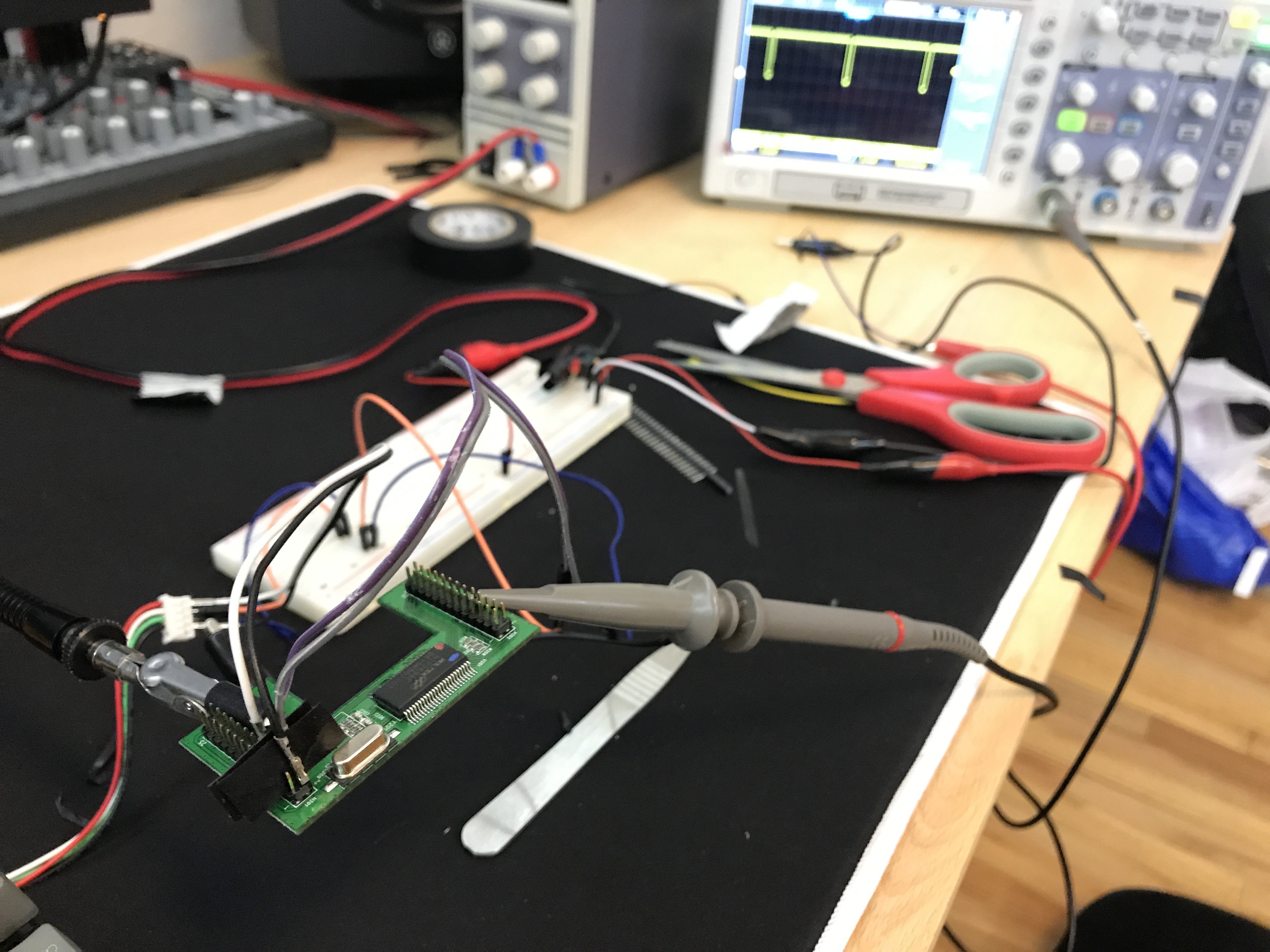
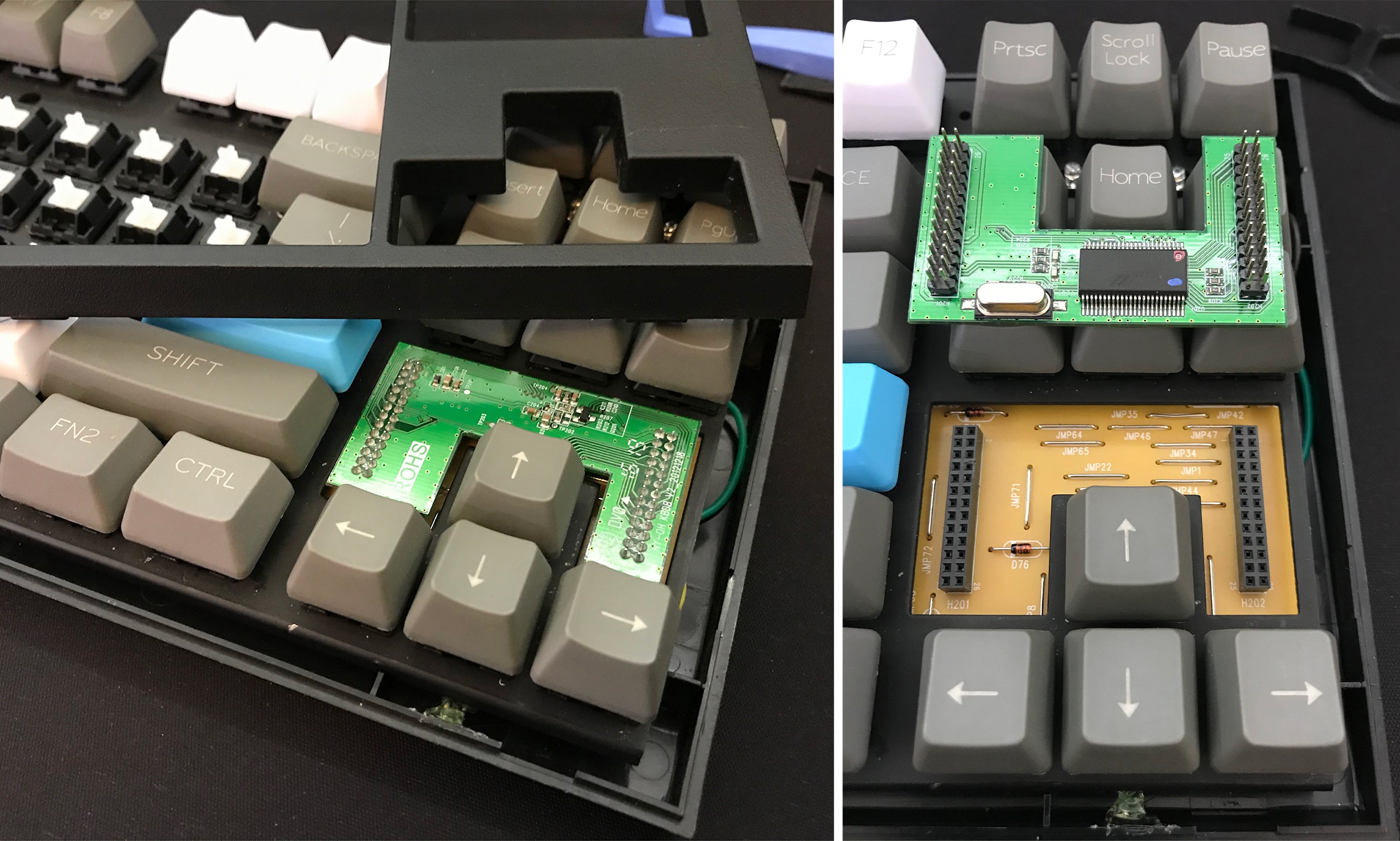
To my utter surprise, what I saw inside was a very easily detachable board with the 'brains' of the keyboard. Upon further inspection I found out that it is using Holtek HT82K94E, which is a micro-controller that is designed for use in keyboards.

    I quickly searched around and found that to date nobody has attempted to flash that micro-controller with a QMK firmware, so I abandoned the idea of reusing it pretty quickly. But nevertheless, as you might have noticed in the previous picture the keyboard has rather inviting pin headers.

    After looking at those headers for a while, I decided to plunge in, and try to reverse engineer how the keyboard matrix is wire, and substitute a Teensy Board. Which is a low cost micro-controller, that is out of the box supported by QMK.

    Part 2: Reverse Engineering

    The basics of how keyboard works is explained quite well in the QMK Readme. Do give it a read if you like the low-level details, but for the purposes of this blog I will assume you have the gist of how keyboards are typically wired.

    The first thing I needed to do was to find which pins were doing the row and column scanning. Although I hoped I could figure out something from staring at the base board, I was in for a disappointment. The circuit-board turned out to be laid out in a very complicated way, with super long traces and jumper wires all over the place to connect traces through the inaccessible (because of soldered switches) front side of the board.


    With passive studying of the circuit board out of question, I resorted to the next best option I had at my disposal—dusting off my oscilloscope. I started probing all of the pins on the controller board, to find ones which have pulses on them, or really anything other than static noise.

    As I was probing the pins I noticed that pins exhibited one of the three behaviors:

    • Produced static,
      • (i.e. touching the pins with oscilloscope probe did not change the signal on screen.)
      • This meant the these pins were unconnected or not pulled up or down.
    • Sustained high voltage
      • Likely the pins which corresponded to the rows sensing pins.
    • Produced a regular square pulse
      • Likely the pins that are used for column scanning

    After probing all the pins I have noted down all of my findings in a google spreadsheet (you can find a link to it in the github repo README). This spreadsheet is going to serve as the base for the next steps, as this was only the beginning.

    In the picture above SL: Scan Line (column), RL: Read Line (row)

    Part 3: Reverse Engineering and Diagramming the Matrix

    After finding...

    Read more »

View project log

Enjoy this project?

Share

Discussions

Similar Projects

Does this project spark your interest?

Become a member to follow this project and never miss any updates