 Oleg Utkin
Being a software engineer, and having most of my time dedicated to typing, I have a deep appreciation for one of my most important toos I use to interact with and create in the digital realm.
I have gotten into keyboards quite a long time ago. It all started from an innocent purchase of a gaming keyboard. I fell in love with mechanical switches from the first click, and have acquired quite a zoo of mechanical keyboards. Some are better and nerdier (**ahem** ErgoDox **ahem**) and some are less so.
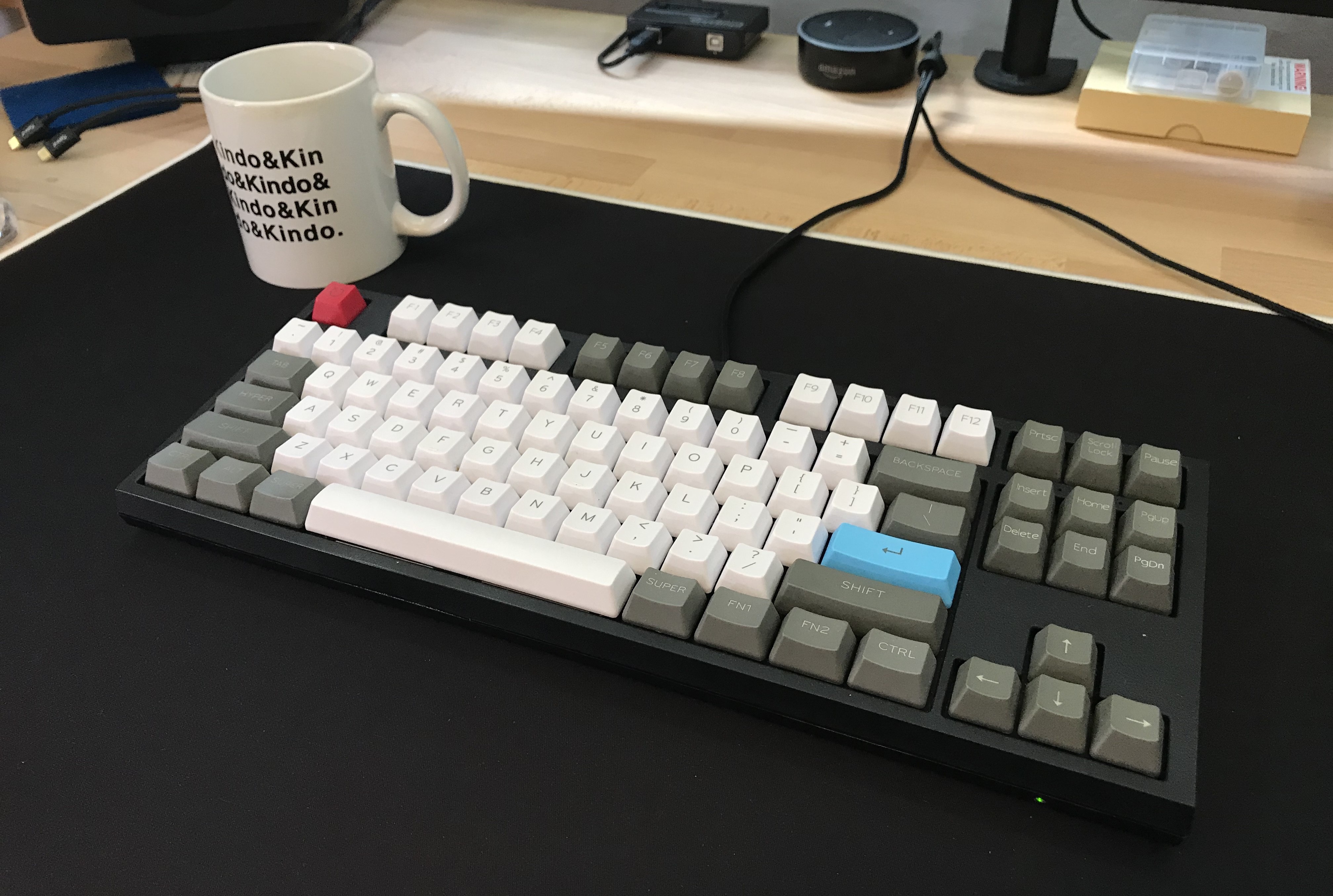
One particular keyboard which I own exists at a perfect intersection of the very well built, but shamefully barely configurable. And that is my WASD Code keyboard. It fell into disuse after I started using Ergodox, and I felt it was unfair, because it is a genuinely good keyboard. And it even has the function keys, which don't require modifiers!!!
In any case, I decided to do something about it. I really wanted to be able to customize it beyond the simple DIP switch changes picking from a few pre-built configurations. I wanted to make it feel like home, like ErgoDox I have at work.
Part 1: Getting The Lay of the Land
After looking through posts of people modifying their vintage keyboards. I thought to myself, I gotta take a look inside, maybe it is using some standard off the shelf components inside. After carefully prying it out of the case I was presented with this: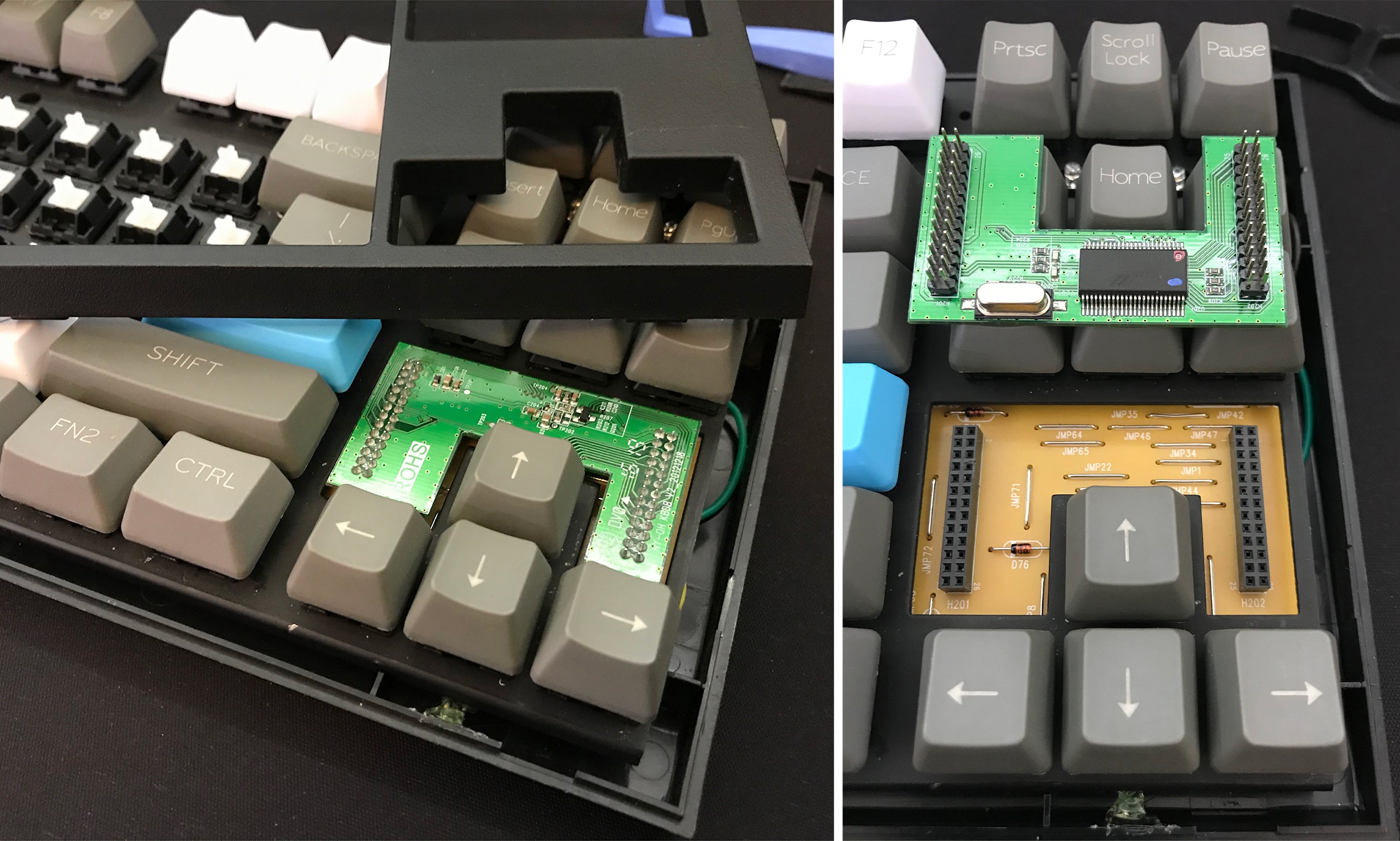 To my utter surprise, what I saw inside was a very easily detachable board with the 'brains' of the keyboard. Upon further inspection I found out that it is using Holtek HT82K94E, which is a micro-controller that is designed for use in keyboards.
I quickly searched around and found that to date nobody has attempted to flash that micro-controller with a QMK firmware, so I abandoned the idea of reusing it pretty quickly. But nevertheless, as you might have noticed in the previous picture the keyboard has rather inviting pin headers.
After looking at those headers for a while, I decided to plunge in, and try to reverse engineer how the keyboard matrix is wire, and substitute a Teensy Board. Which is a low cost micro-controller, that is out of the box supported by QMK.
Part 2: Reverse Engineering
The basics of how keyboard works is explained quite well in the QMK Readme. Do give it a read if you like the low-level details, but for the purposes of this blog I will assume you have the gist of how keyboards are typically wired.
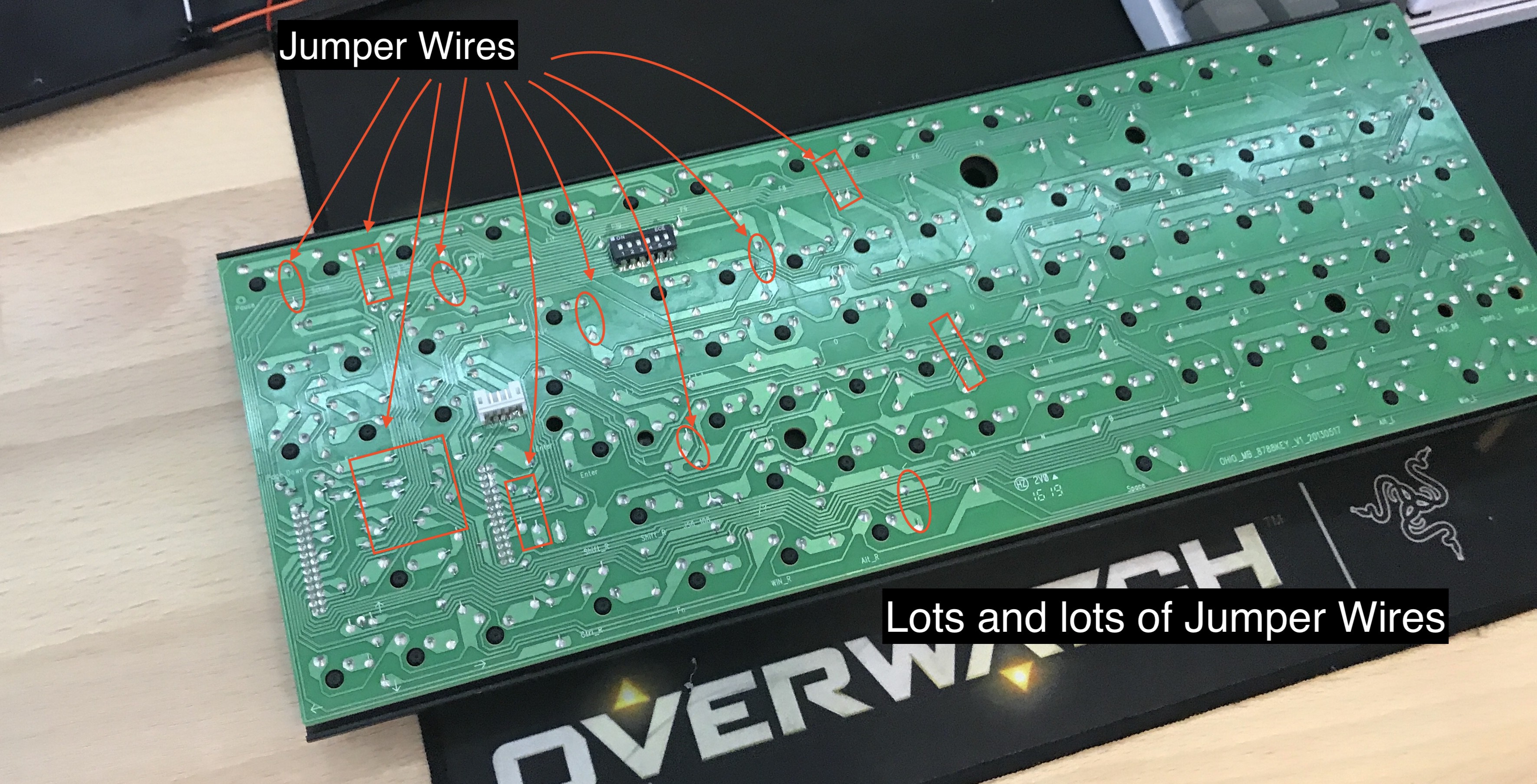
The first thing I needed to do was to find which pins were doing the row and column scanning. Although I hoped I could figure out something from staring at the base board, I was in for a disappointment. The circuit-board turned out to be laid out in a very complicated way, with super long traces and jumper wires all over the place to connect traces through the inaccessible (because of soldered switches) front side of the board.
With passive studying of the circuit board out of question, I resorted to the next best option I had at my disposal—dusting off my oscilloscope. I started probing all of the pins on the controller board, to find ones which have pulses on them, or really anything other than static noise.
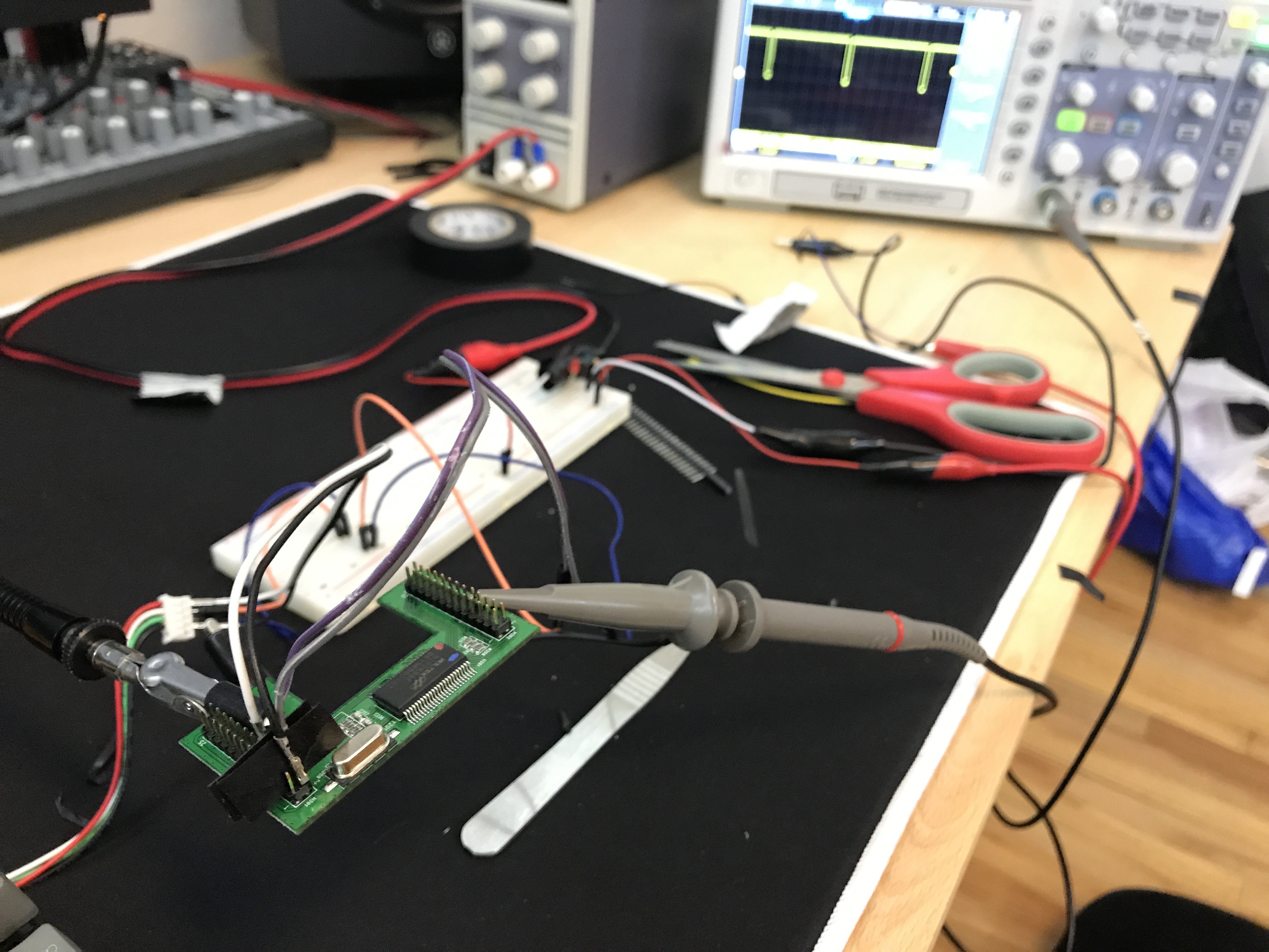
As I was probing the pins I noticed that pins exhibited one of the three behaviors:
- Produced static,
- (i.e. touching the pins with oscilloscope probe did not change the signal on screen.)
- This meant the these pins were unconnected or not pulled up or down.
- Sustained high voltage
- Likely the pins which corresponded to the rows sensing pins.
- Produced a regular square pulse
- Likely the pins that are used for column scanning
After probing all the pins I have noted down all of my findings in a google spreadsheet (you can find a link to it in the github repo README). This spreadsheet is going to serve as the base for the next steps, as this was only the beginning.
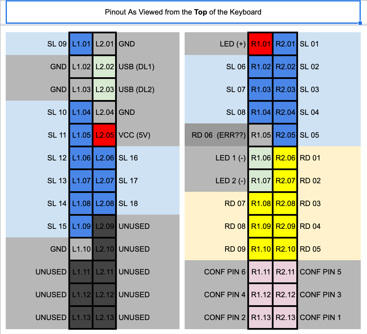
In the picture above SL: Scan Line (column), RL: Read Line (row)
Part 3: Reverse Engineering and Diagramming the Matrix
After finding all of the scanning and sensing pins I only had rows and columns. Now the next task was to reverse engineer the key matrix, I essentially needed to figure out what keys were at what intersections of rows and columns. Which meant I had find which row and column each key connected when being pressed.
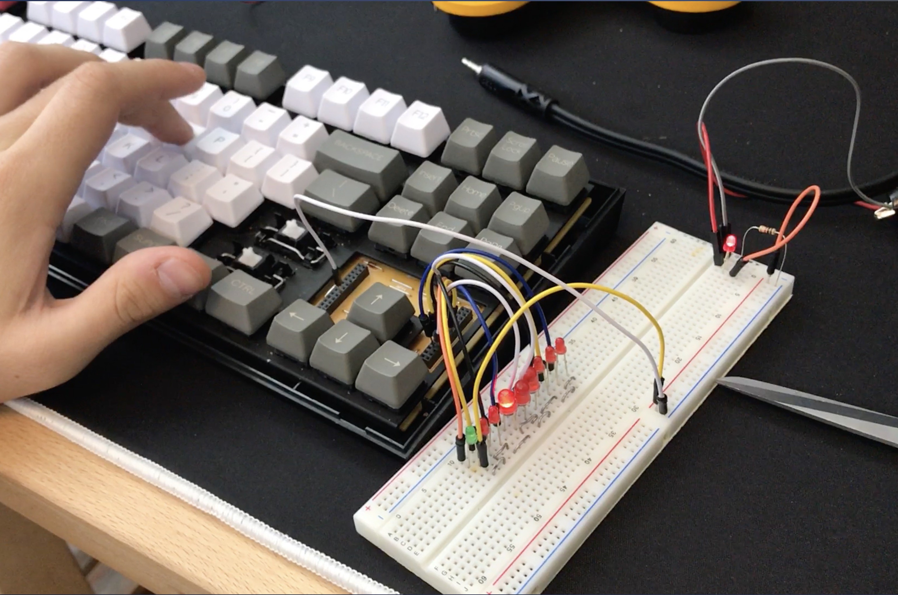
To ease this grunt work, I built myself a clever jig to speed this process, by connecting all rows (since there were much fewer of them) through an LED to a 5V line from my power supply. This in turn allowed me to connect each column to the ground one at a time and mash the keys until I found all of the keys that belong to that column, by watching LEDs light up in the corresponding rows.
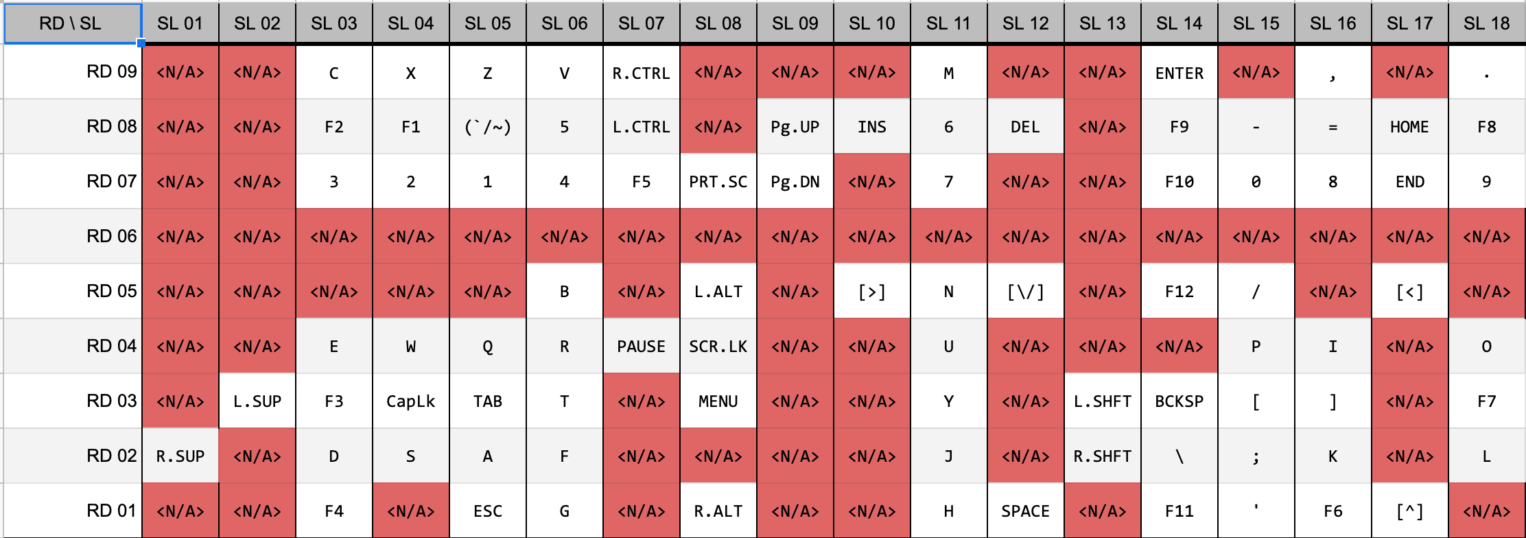
After an evening of grueling grunt work of mashing keys, and recording the results I have constructed this table:
Part 4: Wiring Up
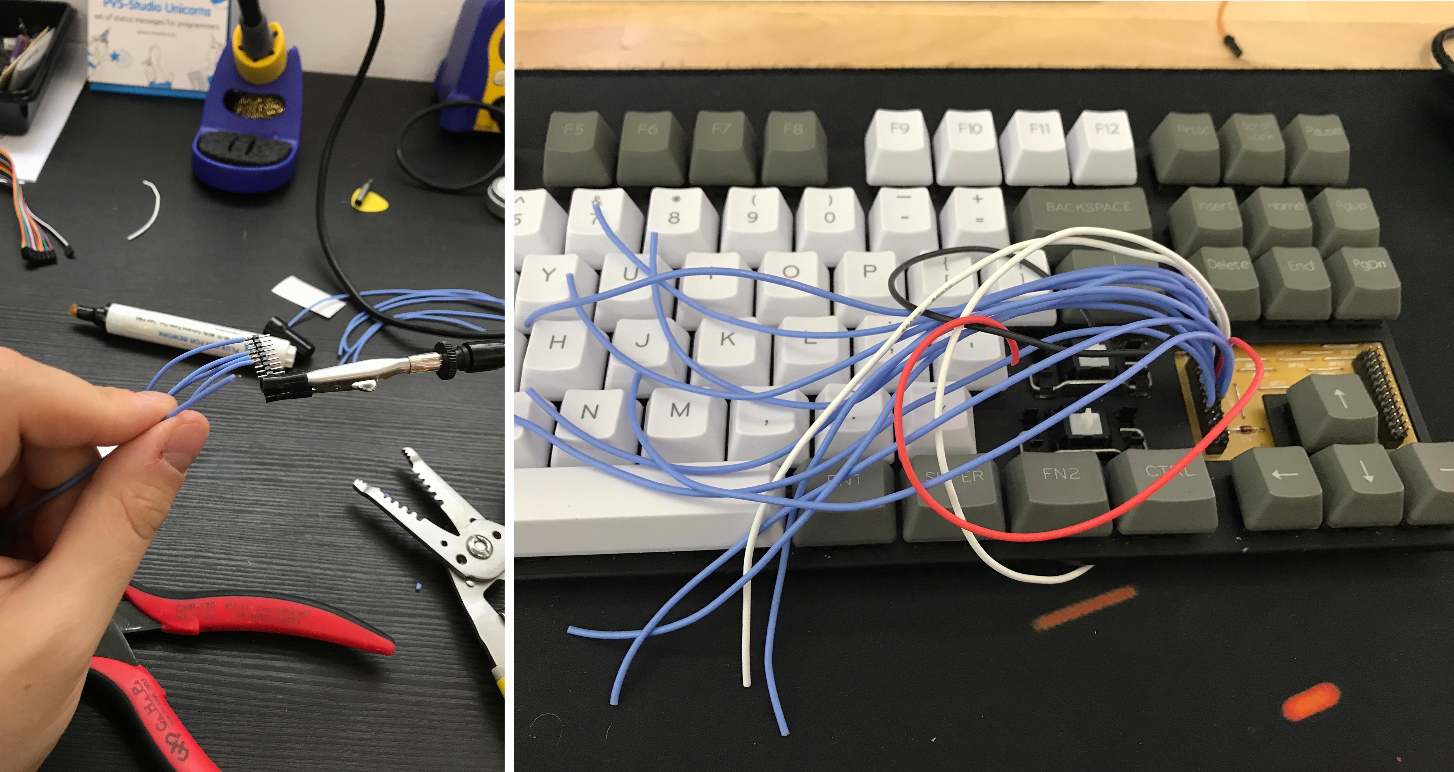
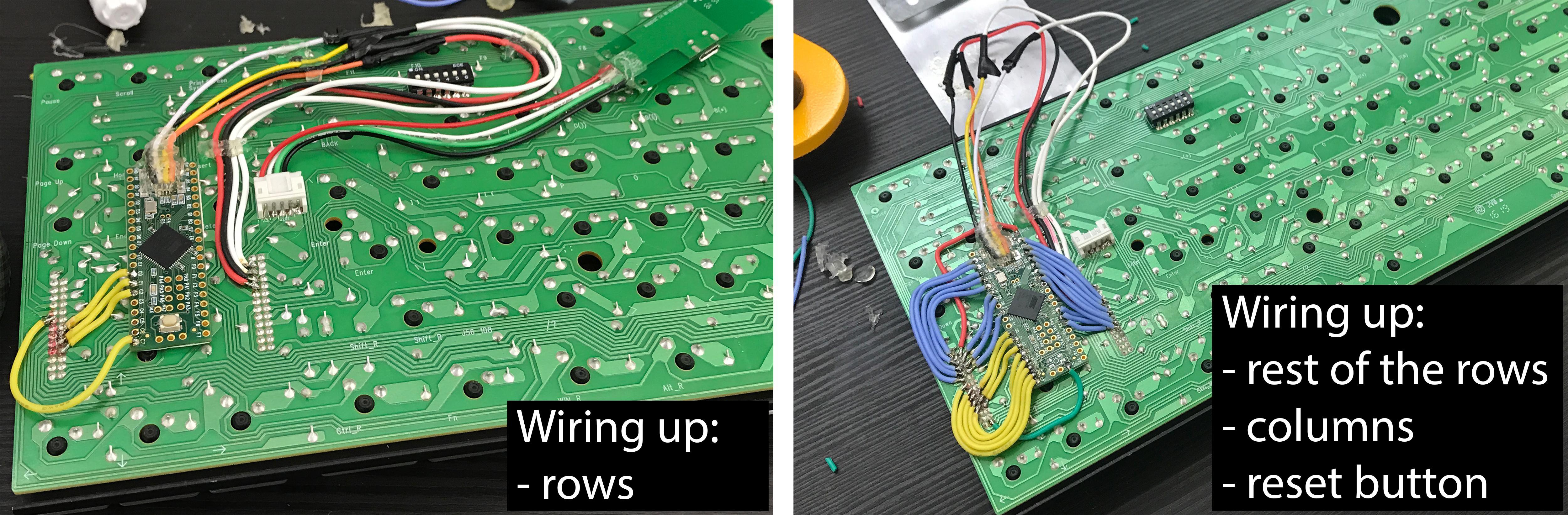
After the reverse engineering was finished, I decided to test out all of my theories, and wired up couple of 'columns' and one 'row' to the Teensy. (beware that in my case the rows turned out to be physical columns on the keyboard and vice versa)
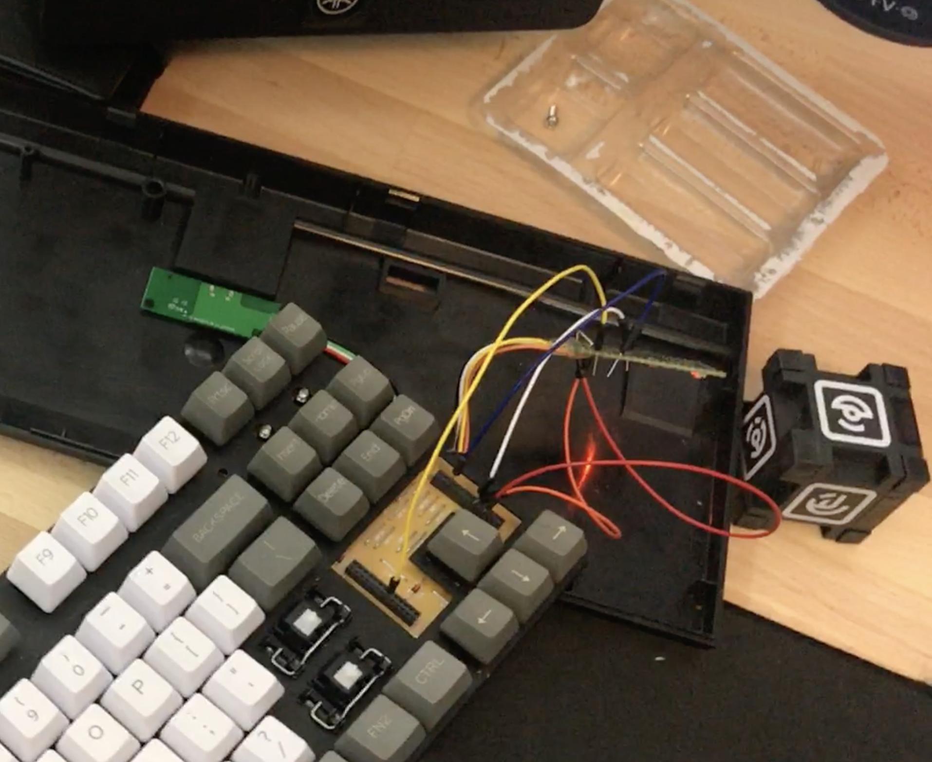

It is working!!! It Liiiiivvvvveeess!
Now it was time for the real deal, the prototype worked, so full steam ahead! Now I needed to actually wire up the Teensy in a way that I could close up the keyboard.
At this point I was sure I had a killer idea how to wire up the Teensie, I have been thinking about it since the first time I opened the keyboard up, I was ready to give my idea a long awaited try... And boy was I wrong...
I though I could get 1 mm pitch pin headers which matched the pith of holes on the base board, solder wires to them and route them around the back of the keyboard. This would let me swap the Teensy with original board fairly easily if I wanted to, and none of the changes would be permanent, meaning I could undo them anytime.
Alright, I am not giving up... I have gone too far into this rabbit hole!
That just did not work at all... The bunch of wires from just one side turned out to be so thick, that there was little hope to close the lid, no matter how much I tried to make it bahave.
(hindsight 20/20 I could have probably used wire wrapping wire, which is ridiculously thin, but I did not have it at the time, nor did I know about its existance...)
Ok so making this modification non-destructively is probably not happening... Back to the drawing board then. It would make sense for teensy to live under the board, that much I knew.
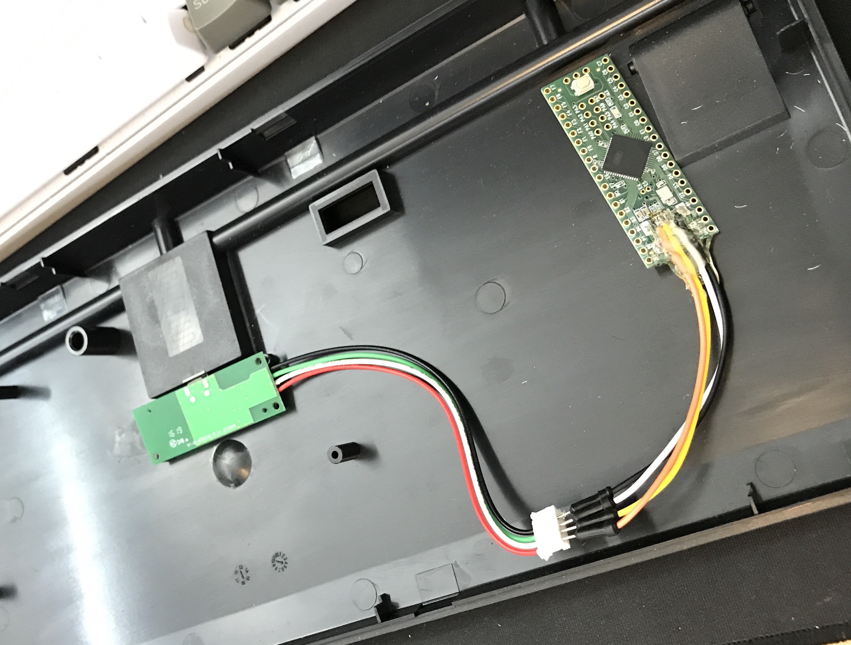
So I started with the basics—the USB connection. For USB connection I decided to solder off the USB header from Teensy and just solder in 4 wires which then connect to the keyboard's USB breakout board.
If I had more time and patience I would probably design a custom PCB for Atmel MCU (like Teensie) with the same dimensions as the original, but it would be a whole lot of hassle, and I haven't had the experience of designing PCBs before.
For the time, being though, I decided to suck it up and permanently solder Teensie to the underside of the keyboard. My previous decision to take off the USB header from Teensie also meant that I could tap into existing pins on the keyboard's base board.
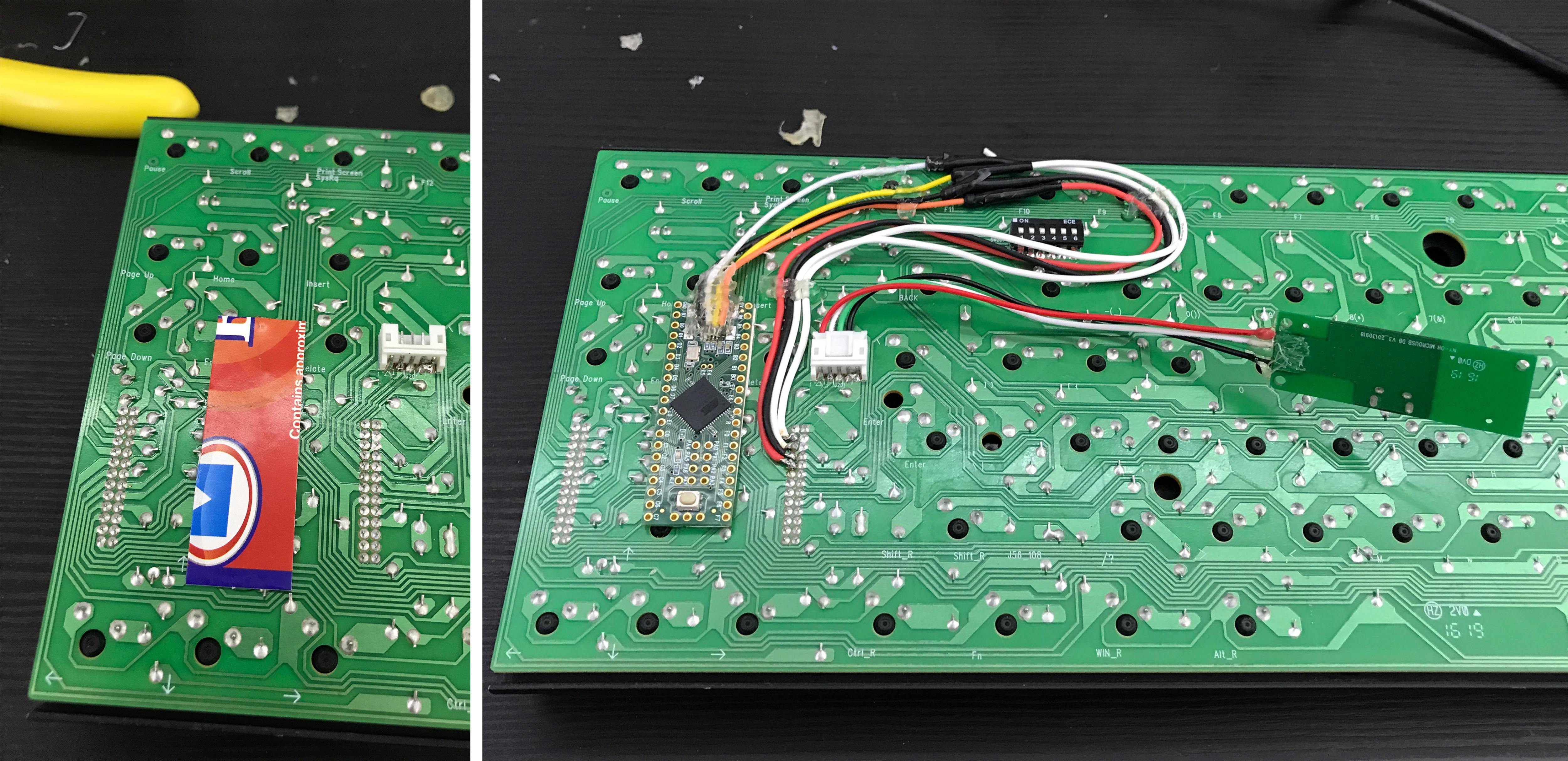
After quite a few hours of cutting up wires to length and soldering I managed to get something workable, and pleasing to look at... and uh... a terrible piercing headache...
WARNING: If you are planning to solder, for the love of god, do yourself a favor... Make sure you have proper ventilation and get yourself a mask! Don't be me.
The story with with the Teensie reset button is kind of funny... As I was debugging my wiring by flashing the QMK with different pin configurations, I tried putting the keyboard together. And from time to time it would just stop working. As it turned out the Teensie being glued to the bottom of the base board, was protruding just enough to be fine for the most part, but trigger the reset button if I applied enough pressure from the top of the keyboard while typing... That was quite frustrating until I figured out what was going on. So I ended up having to de-solder the reset button entirely.
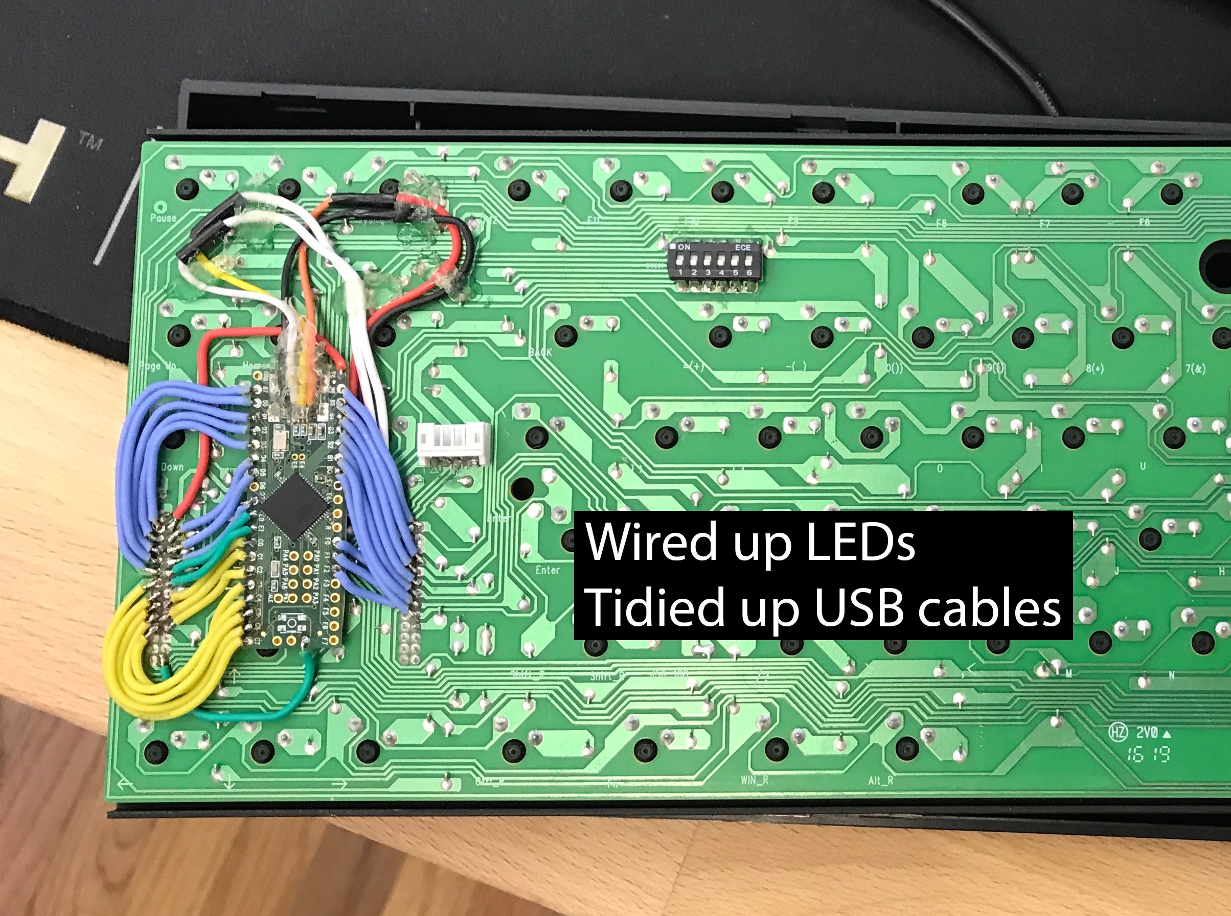
If you take a close look you might notice the extra green wire. It is tied to the reset pin of the Teensie on one end and on the other end to the first DIP switch on the keyboard. That is my extra sneaky way to reset the Teensie for uploading firmware to it in the absence of a reset button.
(3/10 easy to use, 10/10 better than taking the keyboard apart for firmware update.)
After coming back next day, I finished up the soldering, and the result looked something like this:
Part 5: Finalizing Custom Firmware.
The programming of the QMK turned out to be the most boring part compared to the reset of the stuff.
The most difficult part of this whole process was getting the pin configuration right in QMK. I did make a few slip ups when diagramming, but nothing too major that I could not fix.
As it turned out that my diagram in google sheets translated incredibly well to the QMK Framework's macros for setting up keyboard matrix.
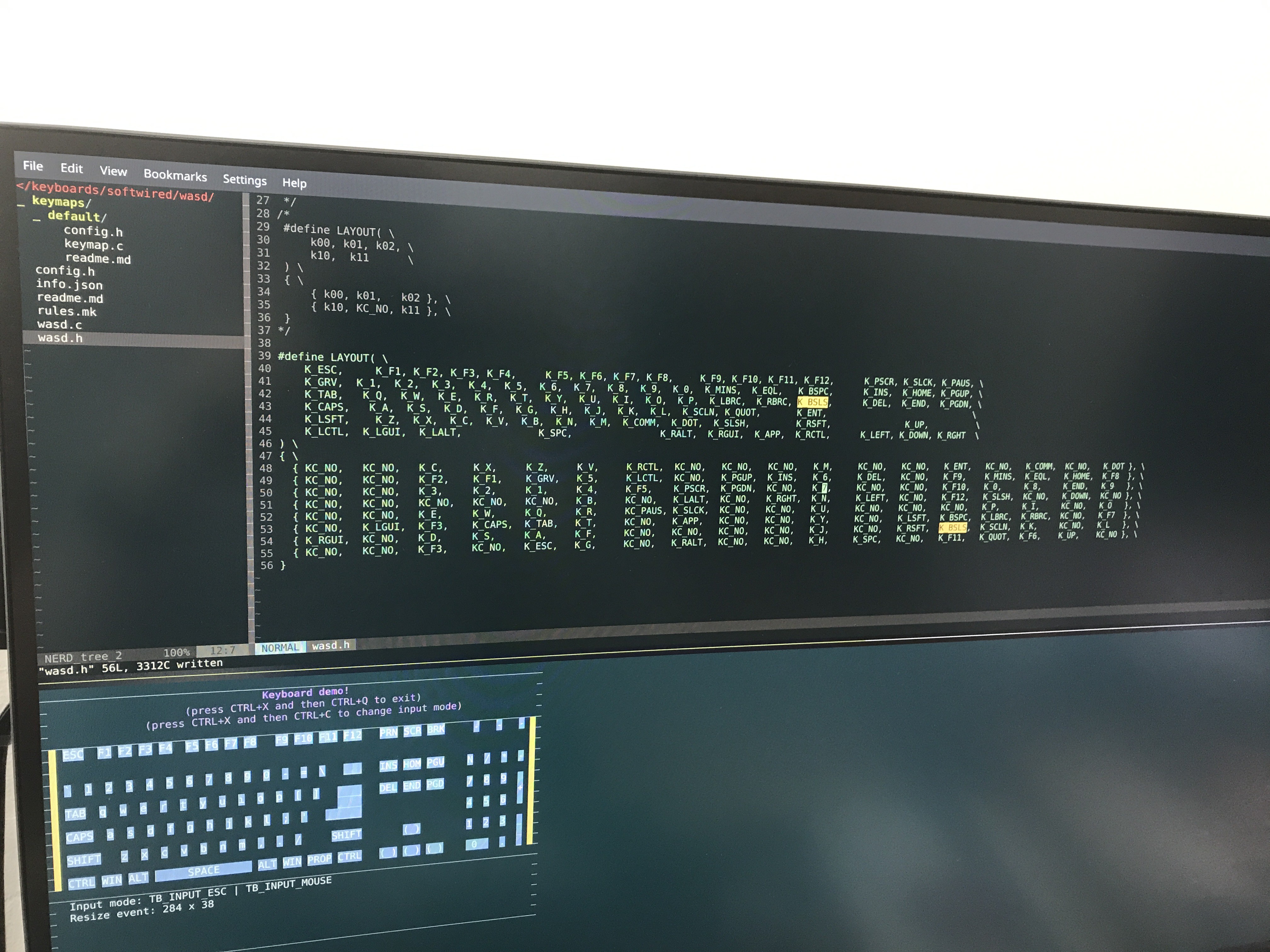
You can find my custom layouts in the my Github Repo in case you want to convert your own WASD Code, you have lying around.
QMK honestly is a really awesome project, it allows you to turn almost anything with buttons into a keyboard.
Can't wait to start working on my Circuit bent Keypad -> Macro Board project in the same vein as this one.
Discussions
Become a Hackaday.io Member
Create an account to leave a comment. Already have an account? Log In.