 fruchti
In November 2011, I bought 5 thermal printer modules from a surplus store because they were 1 € each and what could be more interesting than having a small printer to stick to a project? When they arrived at my doorstep, they immediately went into a ‘potentially interesting things’ drawer.
Hidden from sight, but not purged from my memory, I still occasionally couldn't but think of these neatly documented and not too hard to drive modules.
A few years later it was finally time to do something about these printer modules taunting me from their drawer. The goal was a hand-held selfie camera with thermocromic paper output.
However, I didn't want to build this camera around a Raspberry Pi which would have to boot for each shot or stay on when you might want to take a picture soon. I had something more minimal in mind. As basic as it could get, compact and able to fully turn itself off once it finished printing.
This also had the benefit that I already had nearly all of the parts:
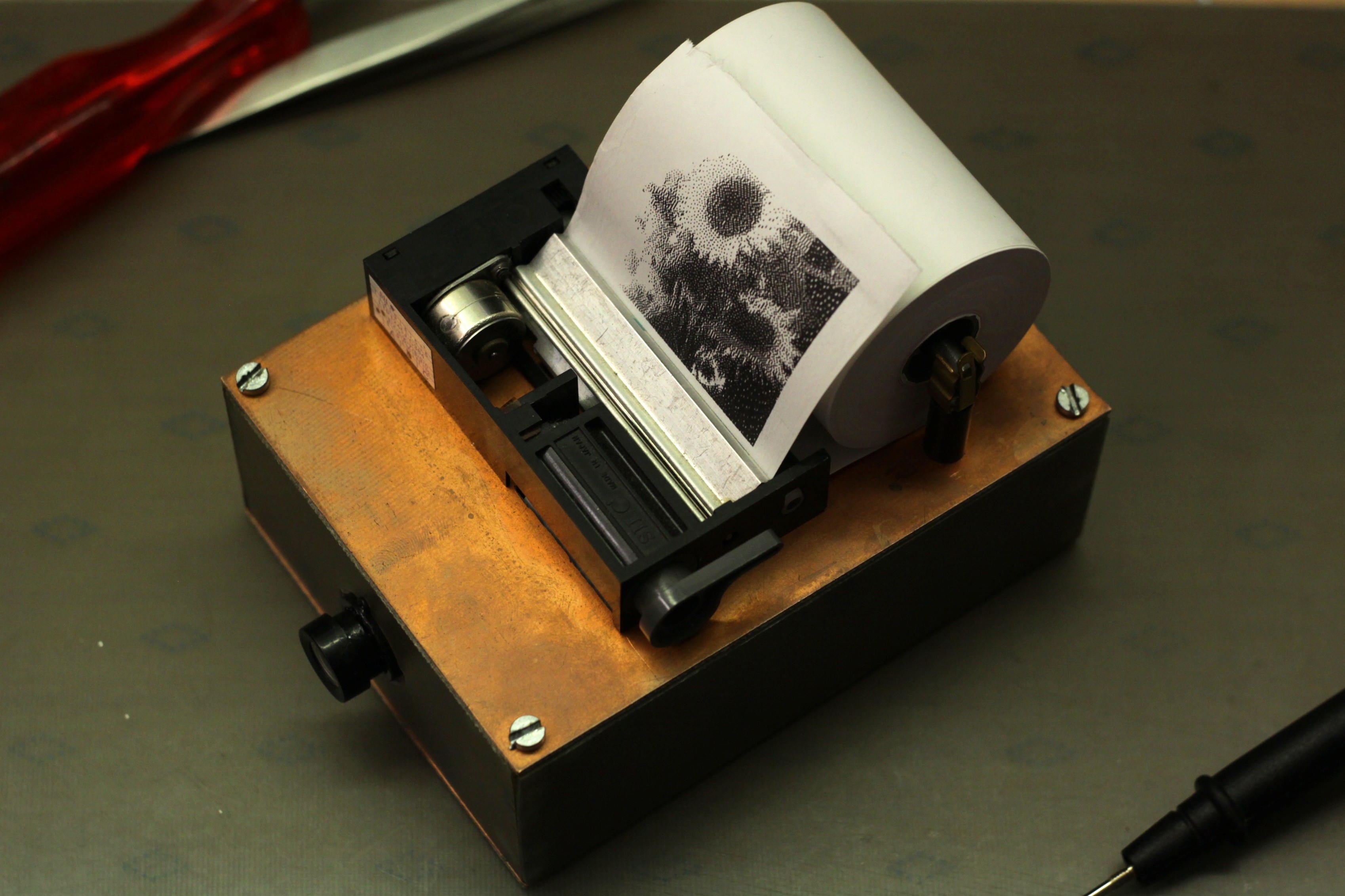
- The aforementioned thermal printer module. Still in its plastic back it couldn't even collect dust over all those years! I had to get the thermocromic paper from a stationery store, though.
- A camera module. I chose a simple, FIFO-less, OV7670-based one to get the project started quickly.
- As the ‘brains’, as STM32F103 on a ‘blue pill’ board. Most of you reading these lines probably already have a stash of these, as did I.
- A 74LS245 (yes, LS) I desoldered from a random junk PCB as a level shifter from 3.3 V to 5 V.
- A 2S LiIon battery pack from an old DECT phone. I was surprised its protection circuit allowed me to draw the amount of current the thermal printer needed. It was an old battery pack and the little capacity it still had quickly went to next to none over a few charge cycles. Still, it was the only compact mobile power source I had which could deliver that sort of power (the battery pack was since replaced by two 18650s with sufficient discharge current capability).
- 4 pairs of BC807/817 from the parts bin to drive the thermal printer's stepper motor (which advances the paper line by line). The motor isn't anything special so I don't need a controller nor a driver IC.
- A random front-panel pushbutton (used old stock) to go on the back of the unit, acting as a trigger.
- Some p-Channel MOSFET shorting the pushbutton as long as the camera operates, keeping it powered. I can't remember the exact part I used but it doesn't really matter as long as it survives the current draw.
- A few random passives, like the 10 kΩ pull-up for the print head's thermistor (because the timing should depend on temperature).
The software side of things
I began by writing a driver for the thermal printer, together with a small font renderer. The documentation thankfully was extensive enough, with proposed timings and formulae for their adaption to varying operating voltage and temperature, that this wasn't to big of a hassle. The text output wasn't used in the final design, but it was very useful to have for debugging.
With the printing part working, it was time for the image capture.
You might be already questioning my microcontroller choice. Using a camera module without a FIFO meant that the image data has to be captured live (unless I would do some sort of equivalent time sampling and end up with the most brutal rolling shutter possible) and a microcontroller without a camera interface isn't exactly built for that.
However, the printer's resolution isn't all that high and the camera module's output resolution can be reduced as well. This took a bit of time since its documentation wasn't all that specific how to configure it near its lower resolution and frame rate limits, but in the end I made it spit out 160×144 pixel frames.
Lacking a camera frame, I captured the parallel pixel data with the MCU's DMA, triggered by timers connected to the OV7670's synchronisation lines. Although I significantly reduced the image size, the STM32F103 still didn't have enough RAM to store a full frame, so I had to apply dithering line-by-line while capturing the data. For the interested: I documented all of this in my blog post in more detail.
While trying to make this all work, I had the camera module connected with a BMOW and DuPont headers on the blue pill's side. Once the pin layout was fixed, I could just solder the connectors to their mating pin headers. Connection secured without having to re-place every wire!
With that done, all what was missing was a basic state machine, which waited a few frames (for the camera's auto-exposure), captured and compressed a single frame, fired up the printer code's state machine with the image buffer and turned off the power MOSFET after its completion. Now it readily spits out images at the press of a button!
Stuffing it into a case
Mechanically, the camera is equally simple:
- The case is built from a few soldered-together scraps of PCB material. The top is held on by 4 screws so it can be taken apart to charge the battery (didn't have any charger ICs or modules I could drop into this project). It still holds up nicely!
- The holder for the paper roll uses two screws with plastic spacers as ‘pillars’, each with a 5×20 mm fuse holder contact on top. The ‘fuse’ being a piece of round steel, wrapped with a bit of tape so it won't wiggle around inside the paper roll's inner tube.
- The inner workings are mainly held together with hot glue (how else would they?).
I didn't squeeze the print head and paper roll into the insides which I don't think hurt the aesthetics of the finished ‘product’ at all.
Wrapping it up
While I of course shared the code of this whole contraption, you probably noticed the lack of a schematic. I didn't draw one for a few reasons:
- The printer module has been out of stock for a few years now. Chances that someone wants to rebuild this exactly the way I did it are pretty low.
- Even if someone got their hands on one of the LTP1245 modules, the circuitry doesn't hold any surprises. For the level shifter and stepper driver you can just use about anything and the remainder is the default configuration from the modules data sheet.
- The more interesting and also more reproducible part of the project, the connection between microcontroller and camera module, is literally just a bunch of wire connecting them straight to each other. Which pin is used for which purpose is documented in pinning.h.
I sadly didn't take any pictures of the insides of the camera and cannot take any right now due to, you know, the situation we are all in right now. I'll leave the image of a blue pill tacked onto a piece of perfboard with jagged edges, surrounded by lots of messy cables and hot glue to your imagination.
Discussions
Become a Hackaday.io Member
Create an account to leave a comment. Already have an account? Log In.