 ziggurat29
I have a separate project which is a TRS-80 Model I emulator. Back in the day, there was a voice synthesizer for it. I have been meaning to add that emulation, and was recently spurred into action by another hackadayer [Michael Wessel] who had produced a hardware version for those with physical machines. While in my case I am making an emulator, his input was still useful to me because I didn't have the phoneme list for the original synth. Anyway, I needed to do a bunch of exploratory work before producing the final code, and part of that involved hooking up a physical SP0256-AL2 to a BluePill so I could record phonemes. That activity seems potentially useful to others irrespective of my TRS-80 code, so I decided to make it a separate project.
For the first iteration I am simply hooking up a SP0256-AL2 to a BluePill as a USB-serial-to-SP0256 bridge. This was to setup for recording phonemes, since I am planning to play pre-recorded signals rather than recreate the LPC filter and whatnot. As such I consider this a 'simulator' rather than an 'emulator'.
It did then occur to me that if that works out, I might be able to put the simulator in toto into the Blue Pill, and not even require the physical '0256. We'll see how that goes -- the BluePill is strapped for space, and even at low bit rates the sound files will eat it up quickly. I will experiment with some compression -- probably ADPCM. We'll see how much the quality suffers.
I also have some Text-to-Speech code from years back, so I will also try my hand at porting that over, too.


 Luke Thompson
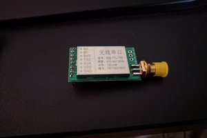
 Dominic DeMarco
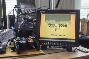
 Wenting Zhang
Thank you very much for this fantastic project! I am a great fan of this old TTS stuff! SP0256 is just as great as S.A.M.! (...do you know this version for a PIC32MX170? http://www.thebackshed.com/forum/ViewTopic.php?TID=8202&P=8)
Your USB version did not work for me - my Blue-Pill is not recognized by my PC! Do you need a special USB-driver for this?
You should mention that your UART version works with 115000 bps/8/N/1 - this version works great for me!! Could you please also create a version with 9600 or 19200 bps? That would be very useful for small (slow) microcontrollers!
Your TRS80 on the Duinomite is just as great! Does the UART work there to connect your SPO256?
THANKS AGAIN!!!