 Frank Adams
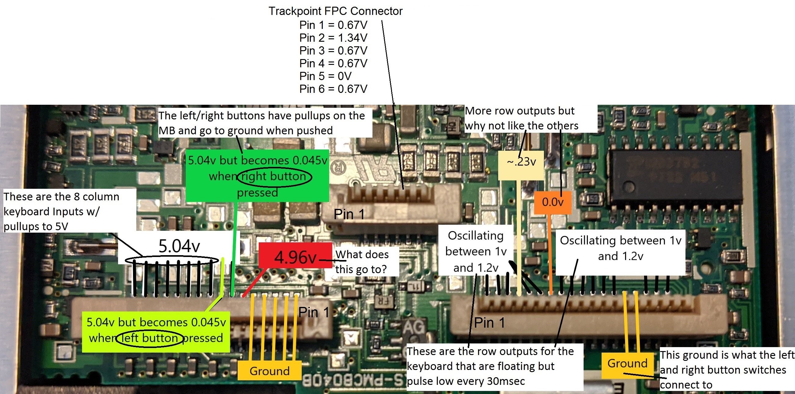
16 pin FPC connector - The first 5 FPC pins are strapped to ground to identify the keyboard as a US language configuration. Pin 6 is for the Fn key. The right and left trackpoint buttons on pins 7 and 8 are pulled up to 5 volts and go to ground when the buttons are pressed. Pins 9 thru 16 are the 8 columns for the key matrix and are pulled up to 5 volts.
18 pin FPC connector - Pins 1 thru 3 and 6 thru 18 are the key matrix rows that are each pulsed low so the columns can be scanned for a closed switch.
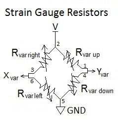
6 pin FPC connector - Pin 2 is power and pin 5 is ground. Switching to resistance measurements showed that pins 3 and 6 are tied together and pins 1 and 4 are tied together. These two sets of pins go to the X and Y strain gauge variable resistors.
Crude Trackpoint Testing: A crude test board was created with an FPC connector and jumpers to a Teensy 3.2.
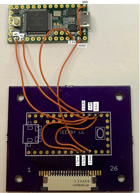
FPC Pin 2 goes to Teensy 3.3 volts. Pin 5 goes to Teensy ground. Pins 3 and 6 go to Teensy ADC A1 and pins 1 and 4 to Teensy ADC A0. Resistance measurements show the individual strain gauge resistors are 352Ω when at rest. If the trackpoint is forced hard left, right, up, or down, the resistance will change about 1Ω. When powered with 3.3 volts, the voltage divider will only change ± 4mV. I expected this would be difficult to reliably detect with the Teensy but gave it a try anyway. I used code I had previously developed for converting the pointing stick (aka trackpoint) from a Dell D630 to USB. The Dell trackpoint uses 4 KΩ strain gauge resistors that cause a change of ± 30mV which is a lot easier to detect. The code reads the X and Y voltages at startup and saves these as the “at-rest” values. There is a dead zone around the at-rest values so noise doesn’t cause unwanted cursor movement. The Thinkpad trackpoint was able to move the cursor with this code but too much force was needed. Reducing the dead zone allowed less force but noise would move the cursor when at rest.
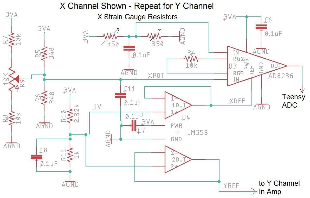
Instrumentation Amplifier: The standard method for reading a strain gauge is to use an instrumentation amplifier. I chose to use the AD8236 because it’s low cost, works on a single supply and has a reference pin for offsetting the output. The schematic for the X channel amplifier is shown below. The Y channel is the same. The LM358 Dual Op Amp provides a low impedance 1 volt DC reference voltage to each AD8236. This raises the output up to 1 volt when the inputs are balanced in order to operate from a single 3.3 volt supply. The gain of the AD8236 is set to 47 with a 10KΩ resistor. The 10KΩ potentiometer provides the fine tuning to set the minus input to the exact same voltage as the positive input when the strain gauge is at rest.
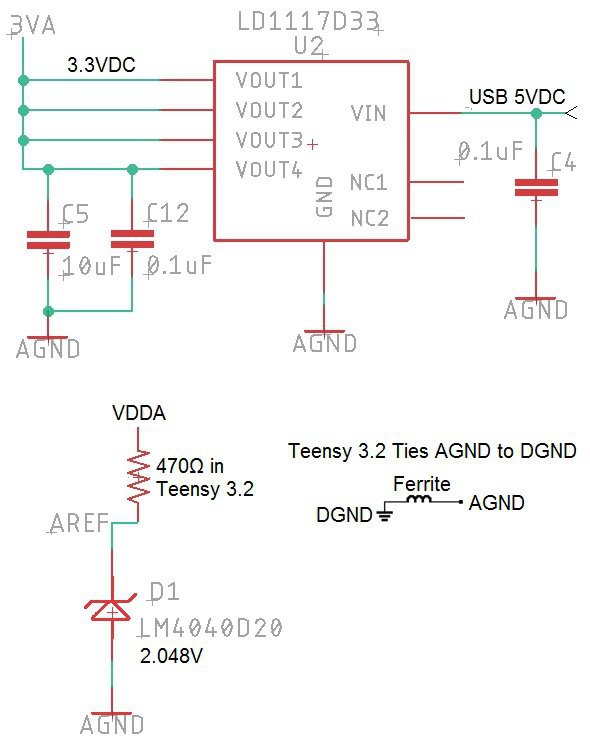
An LM4040D20 shunt style voltage reference is used on the Teensy 3.2 AREF input to give 2.048V for the ADC reference instead of the standard 3.3 volt reference (see schematic below). The 13 usable bits of the Teensy ADC will span 2.048V instead of 3.3 volts. This changes the resolution to 0.25mv/bit instead of 0.4mv/bit. An LD1117A linear regulator is used to drop the USB 5 volts down to 3.3 volts for powering the trackpoint circuit. This was done instead of using the Teensy’s 3.3 volt regulator in order to reduce the digital noise in the amplifiers. Note that the Teensy ties analog ground to digital ground with an inductor as shown below.
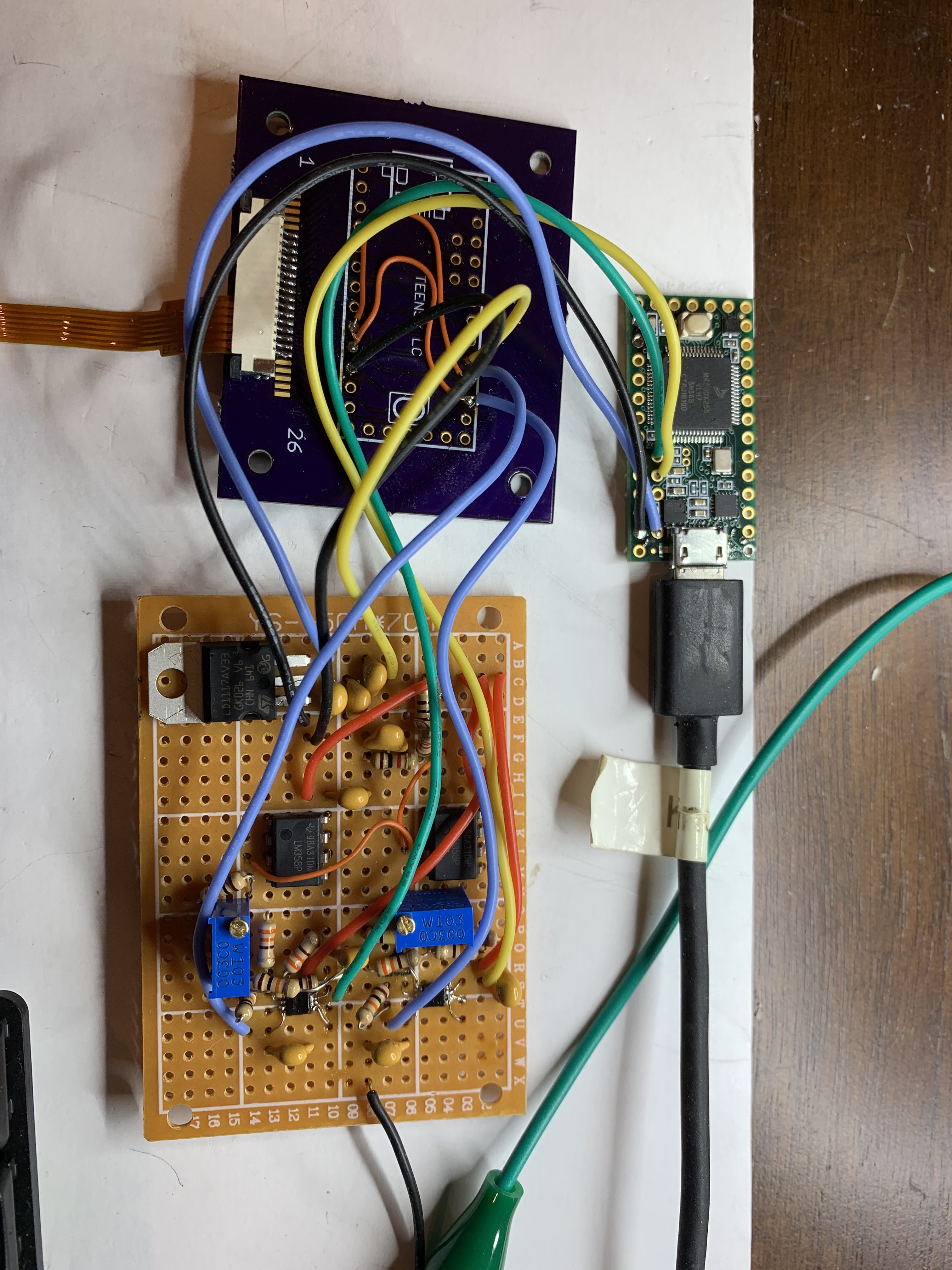
Breadboard Circuit: The AD8236 is not available in a DIP but I really wanted to make sure the circuit would work before getting a board fabricated by OSH Park. The breadboard shown below was a test of my soldering skills but after fixing a couple shorts and opens, I managed to get it to work.
Both potentiometers smoothly adjusted the instrumentation amps to output 1 volt with the trackpoint at rest. Pushing the trackpoint hard in each direction gave these voltages out of each AD8236.
| Trackpoint Direction | AD8236 X Channel | AD8236 Y Channel |
| Right | 1.13V | 1.0V |
| Left | 0.78V | 1.0V |
| Up | 1.0V | 1.18V |
| Down | 1.0V | 0.84V |
The dead zone in the code was adjusted way down to give a feather light touch on the trackpoint. For temperature testing, I used a heat gun blowing on the keyboard. After a few seconds, the strain gauge resistors deviated slightly which caused a voltage difference on the instrumentation amplifiers. This was gained up to about 10 mv as measured with a meter on the output pin of the amp. This voltage caused the cursor to slowly move up and right until I restarted the Teensy to force it to capture the new at-rest voltage. This problem will be solved in the final version of software by allowing the user to zero the cursor with an Fn-F12 key press. I’ll also make it possible for the user to decrease the dead zone using Fn-F9 or increase it with Fn-F10. I’m not a fan of potentiometers and even looked at switching to a Teensy 3.5 to eliminate them. The Teensy 3.5 has 2 DACs which could each be connected thru a resistor to the x and y fixed voltage dividers so that software could nudge the set point up or down. After seeing that the effects of temperature were not very severe, I believe the existing circuit won’t drift outside of the 0.2 to 1.8 volt usable ADC range. This range still gives 200mv of head room for normal trackpoint operation.
Eagle Schematic and Layout: I created the footprints and symbols for the components I couldn’t easily find online. All the relevant keyboard row and column FPC pins are routed to Teensy I/O pins for maximum flexibility. The general placement of the connectors is driven by the FPC cables. Spare digital and analog I/O are brought to thru-hole pads for future use. 715Ω resistors are included for 2ma Caps, Num, and Scroll Lock LEDs. Area fill polygons are used for analog and digital ground planes on the front and back side. All of the analog components for the trackpoint are located together with the exception of the 6 pin FPC connector. I placed each surface mount part on a 1 to 1 scale paper layout to verify I had the correct pad size and spacing as well as clearance between parts. I’ve skipped this step in the past and ended up with placement problems that could have easily been fixed. With the paper layout showing no problems, the Eagle board file was sent to OSH Park for fabrication. 3 boards cost $27 to fabricate. The board is 50mm x 70mm and uses the default settings.
Circuit Board Assembly: The blank OSH Park circuit board is shown below. Wow, they make beautiful boards!
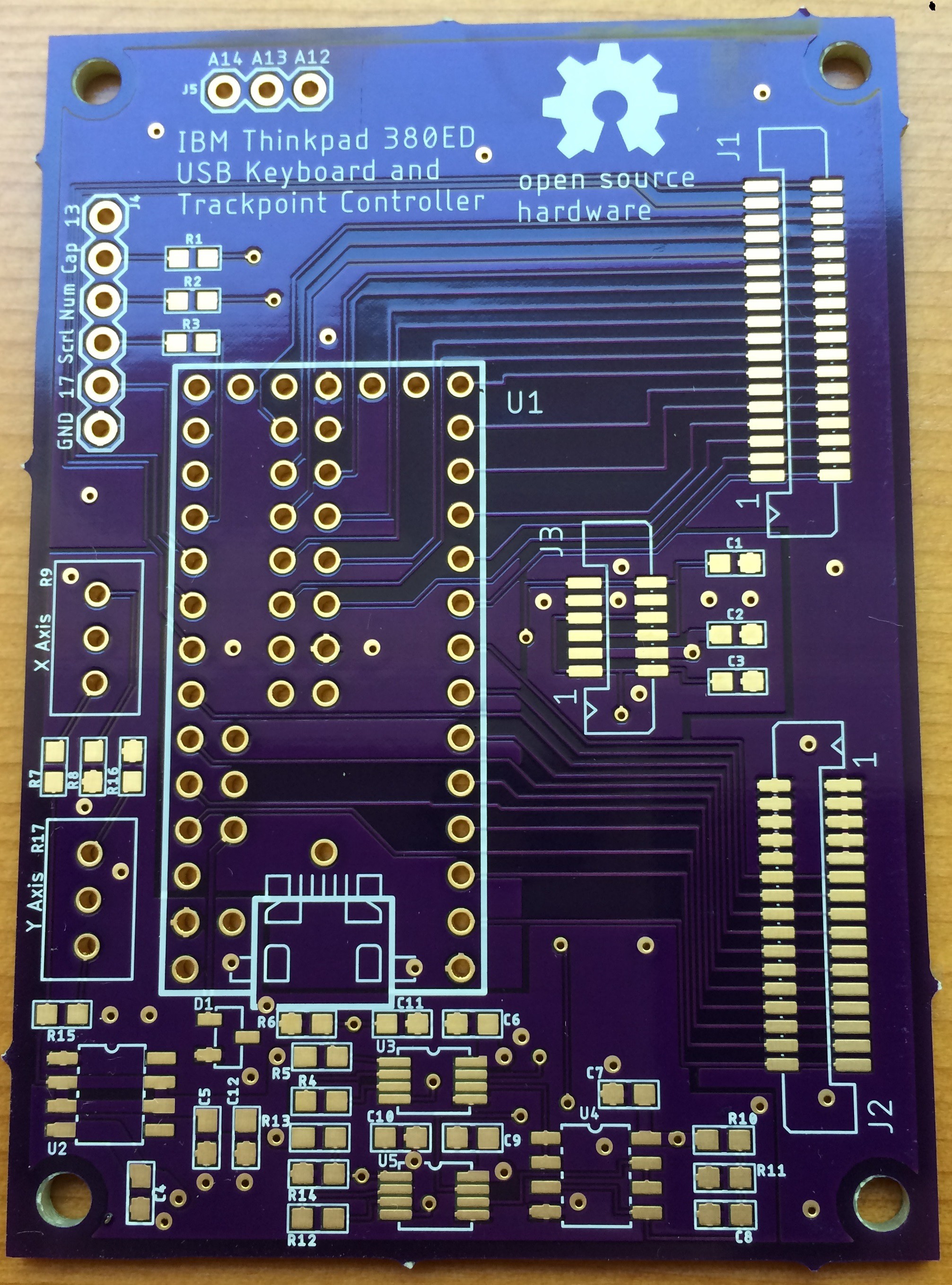
I used standard tin-lead solder paste, applied with a syringe and toothpick, then re-flowed with a converted toaster oven. I had to clear a few solder bridges where I applied too much paste. The old saying "the bigger the blob, the better the job" does not apply with surface mount devices.

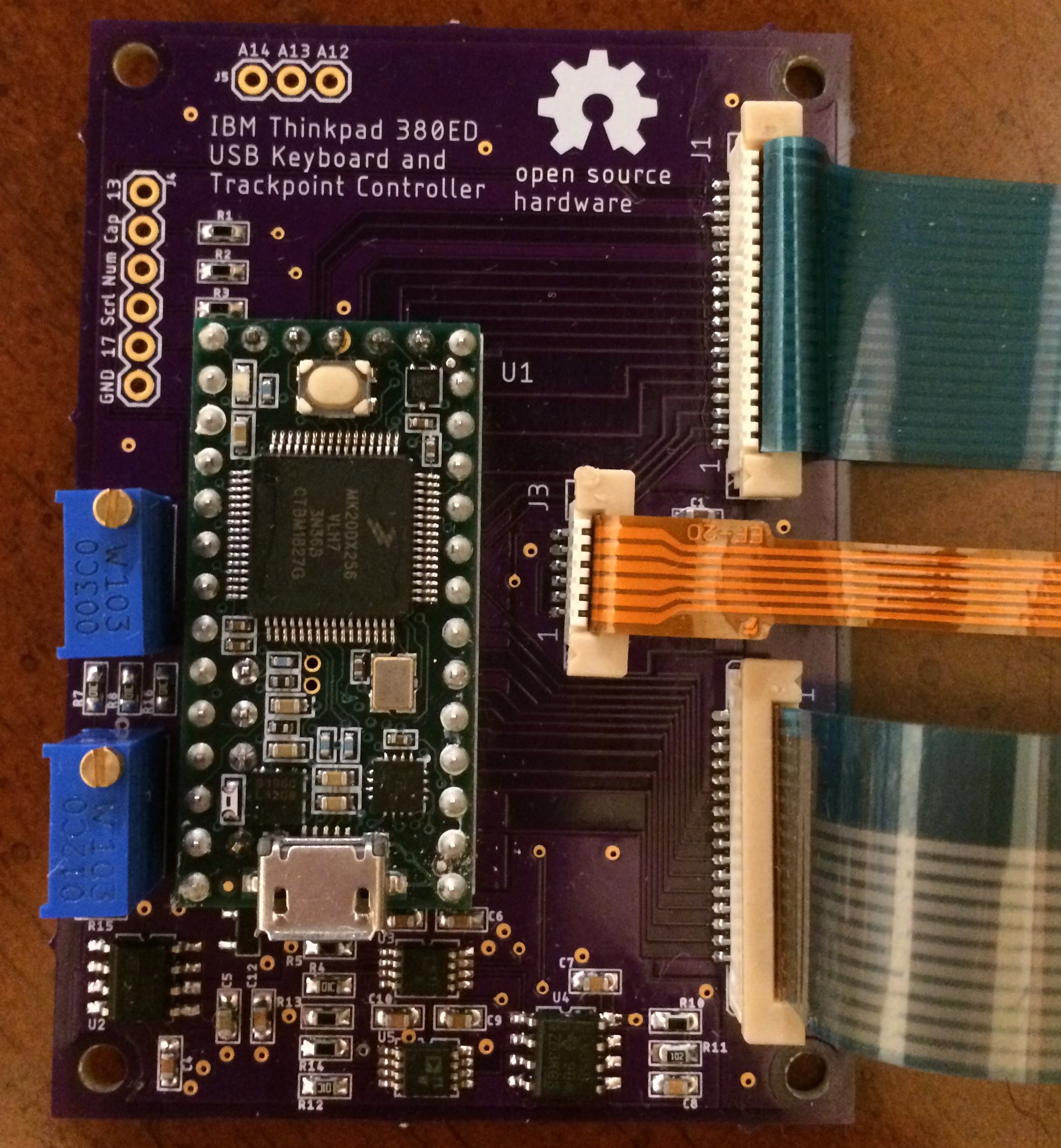
The assembled board with the Teensy 3.2 and FPC cables is shown below. I designed the layout so that 2x7 right-angle header pins can be used for the surface mount pads on the Teensy backside instead of flying leads.
Trackpoint Testing: The trackpoint code "Trackpoint_380.ino" from the breadboard circuit was loaded into the Teensy and the potentiometers were adjusted to give 1 volt to the X and Y ADC inputs. The trackpoint operation was identical to the breadboard and worked great. Checking the X and Y ADC inputs a day later showed 0.999V and 1.002V. This voltage will be checked over time to see if it changes.
Key Matrix Decode: The Teensy 3.2 was loaded with the routine "Matrix_Decoder_3p2_380.ino" that scans thru the I/O's and reports over USB, the two pins that are connected when a key is pressed. The resulting I/O connection list was transferred to the keyboard matrix below. The Teensy I/O numbers and FPC connector pins are given for J1 (18 pin FPC connector) and J2 (16 pin FPC connector).
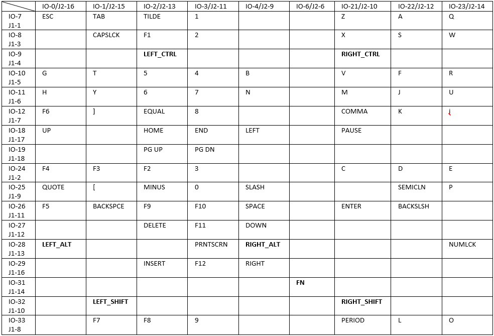
The right mouse button is on I/O-5 (J2-7) and return is on I/O-30 (J1-15).
The left mouse button is I/O-20 (J2-8) and return is on I/O-30 (J1-15).
USB Keyboard and Trackpoint Code: The key matrix table was transferred into the USB keyboard code described in my Instructable. All keys work normally, including the Num-Lock keys. I added mute, volume up, and volume down for Fn-F1, F2, and F3 even though they are not labeled on the keys. The trackpoint code was merged with the keyboard code to give a composite USB device. Function key inputs from the keyboard allow for adjusting the trackpoint variables. Fn-F12 re-captures the "at rest" position in case the user notices any drift. Fn-F9 reduces the noise zone value by 5 and Fn-F10 increases the nose zone by 5. This reduces or increases the amount of pressure needed to move the cursor. Fn-F11 brings the noise zone back to the startup value. Brian is continuing to test and improve the Teensy code. He found that the original trackpoint code didn't work well when the movement was near the x or y axis. The algorithm was changed to fix this problem and the scan rate was increased for smoother operation. Any improvements will continue to be uploaded to my repo.
Stephen has designed a stand alone case for this keyboard. His 3D print files are at thingverse.