Close
0%
0%

Truncated Icosidodecahedron Lamp

A lamp made of 930 laser cut parts in a heavily geometric design

Public Chat
Similar projects worth following
I was browsing Wikipedia reading about smart old dead guys. Came upon a chart of Archimedean solids. The Truncated Icosidodecahedron sparked my interest. I've made table lamps, lamp shades, even night lights...but never a floor standing lamp, NOW I HAVE!!!

I designed something like this a while back but there were just too many parts to consider it.  Well, now I have time!  I restarted the design from scratch with a different solid as the focus.  Then I saw the Making Tech At Home contest, and had to make some extra changes before cutting.

The cloth I was going to order for the diffuser material was replaced by tissue paper originally intended for shipping earrings and Xmas ornaments on Etsy.

The rotary power switch and knob I was going to order were replaced by the power switch from an old dead ATX power supply.

The 3 meter extension cord I was going to order to cut and use as a power cord was replaced by the cord from an old TV spliced into some wire from an old extension cord to get the total length I needed.

The light bulb was from my pantry; we keep extra bulbs on hand.  It's one of the cheap GE ones; nothing fancy.

The light bulb socket was a leftover from a 4-pack that was only a few cents more than a 1 pack.  One went into a table lamp, another into version 2 of that lamp, and now a third is in this...maybe a 4 pack will end up having been too small.

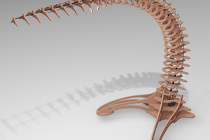
The wood was all stuff I had on hand; back in the good old days when going to Home Depot was something sane people did I bought as much of it as I could fit on my shelves and I still have a good amount left.  I also have tons of this wood as scrap from other projects.  One feature of this project is that many of the parts are small, so I got to use those scraps.  I think getting rid of the scrap was a higher priority than reducing use of new sheets of wood; my scrap buckets are no longer overflowing!  It's 4.5mm thick birch plywood, stained with Minwax Crimson stain.

Cutting took the better part of a day.  It would have been a lot faster but I spent a lot of time trying to fit pieces onto bits of scrap.  Assembly took something like 30 hours.  Didn't really mark times or anything but it was most of three days used on assembly.  Staining all the pieces also took a long time, but it's hard to say how long since a lot of them were already stained.

The design is parametric, with variables for things like wood thickness, minimum material thickness, and even a built-in kerf offset (because RD Works gets confused sometimes so it's easier to just do it in SolidWorks).  Basically just put in a material thickness and a kerf, press regen, and then save a DXF containing all the parts with a very light press fit that can be assembled without tools.

As far as releasing files: I don't want to release the original SolidWorks file because it would only help people with SolidWorks 2019 or newer...even other software that can import it will likely drop all the parametric stuff that makes it work.  I think that maybe the best way would be to turn off the kerf compensation, set the material thickness to 4mm, and export that...then repeat for 4.1mm, etc, etc up to 6.1mm...but that's 20 DXF files to make and it's getting late so maybe in the morning.

Truncated Icosidodecahedron Lamp V0.001 HaD UPLOAD.dxf

All the pieces for various material thicknesses

AutoCAD DXF - 14.35 MB - 05/06/2020 at 15:53

Download

  • Assembly Instructions

    Zack05/06/2020 at 16:34 0 comments

    I should probably touch on assembly.  The parts are numbered in the DXF and I'll be using the same numbers here.  I will give instructions with the assumption that only one side of your material is painted/stained/sanded/etc and the other side is unfinished and should be hidden.  The finished side will be called the front, the unfinished side will be the back.  You will want to glue as you go; if I say something like 'place' or 'assemble' I assume you will use glue in the process.  Parts 20, 06, and 08 should be finished on both sides as both sides will be visible.

    0.) The paper parts (21-24) need to be glued to their matching wood parts (01, 04, 05, 07).  The wooden part connectors will hold the paper parts but without glue the corners will sag.  Glue the paper to the back side of the wood parts.
    1.) Place part 1 on a table, front facing down.
    2.) Place 5 of part 15 into the holes around the border, skipping 1 hole between.
    3.) Place 5 of part 16 into the remaining holes around the border.
    4.) Assemble 5 of part 05 onto the the 5 part 16's placed in the last step, front facing out.
    5.) Place 10 of part 13 into the holes in part 05 that are closest to part 1.
    6.) Assemble 5 of part 07 into the 5 square shaped spots created by previous steps, front facing out.
    7.) Repeat same basic steps using the image of the final product as a guide.
    8.) When the only part left is the top-most decagon, stop using parts 15 & 16.  Use part 19 in the remaining holes in the part 07's, and use part 18 in the remaining holes in parts 05.
    9.) Slide part 20 into the center of part 02.
    10.) Assemble your light socket into part 01 as needed.
    11.) Assemble parts 03, 06, and 08 the same way as the top.  There are fewer parts but the way the parts fit together is the same.
    12.) Place 4 of part 14 into every part 11.
    13.) Assemble a ring of 5 of the assemblies from the last step, using part 10 to connect them.  See the image of the final product for orientation.  You only want part 10's on the bottom of the ring while assembling it, then you can add the remaining 5 part 10's that the ring needs one by one.
    14.) Place 5 of part 17 into the remaining holes in the 5 part 10's at one end of the ring you made.
    15.) Place one of part 10 onto one of the part 17's from the last step.
    16.) Build a ring like the previous one (but also connected to the previous one), working around as you go.
    17.) Keep adding rings until you have added all you want.
    18.) Part 09's go on the ends of the shaft you made.  They slot in just like part 11 did, using the same part 14 connectors.
    19.) Slide the shaft into the 5 slots in the top of the base.
    20.) Place two of part 12 on either side of each part 09, securing them together with screws and nuts (and washers ideally).
    21.) Repeat the last two steps, but with the top.
    22.) Run your wires.
    23.) Test.

  • Hot glue melts when hot

    Zack05/06/2020 at 16:04 0 comments

    Found a minor hiccup with the lamp I made.  This morning when the sun was beating down on it the shaft seemed a bit too wobbly.  I think it is down to the glue.  Aiming for the "don't buy anything" goal meant I didn't have much fast drying wood glue to work with.  It would have taken months to assemble if I had used the wood glue I had on hand.  So I used hot melt glue for a lot of it.  The bits where I used wood glue are solid, but the hot glue flexes a little and flexes more when warm.  I'm still pretty confident in the design if assembled with a glue that dries hard, but I'm not about to disassemble it to replace the glue.  Instead I took the handle from a broken rake, cut it to length, painted it black, and glued it to the inside of the shaft.  Now it's a lot more stiff.

    Again, I'm 99% sure this is down to the hot glue given that the issue is a lot more obvious when sitting in the Florida sun on a hot day in a room of windows with no air flow or AC, but thought I should mention it.

  • Uploaded the DXF

    Zack05/06/2020 at 15:55 0 comments

    I exported DXF files in material thicknesses ranging from 2.9mm - 4.7mm, put them all in one DXF file, and added some notes.  If you have questions, just ask.

View all 3 project logs

Enjoy this project?

Share

Discussions

Similar Projects

Does this project spark your interest?

Become a member to follow this project and never miss any updates