We all liked that feeling of nostalgia for the games and games we played in childhood and adolescence. Several consoles and computer games marked this era. One of the great games was the Minesweeper of the Windows Operating System, which is shown in Figure 1.
In this game, we aimed to select a location that did not have a bomb. Otherwise, we lost the game.
Therefore, it was thinking about the concept of this game, that we created this project with the objective of bringing back a game that is well known to all: the minefield.

Figure 1 - Minesweeper of the Windows Operating System.
Our project consists of a simple game with excellent dynamics, with the option of being played by two people.
Your main objective is to choose an empty square where there is no bomb. If there is a bomb in place, the game is over. Otherwise, the game continues. Based on this, each location will be represented by a button connected to the Arduino.
Therefore, in this article, you will learn the following concepts:
1. Develop the minefield game for Arduino;
2. Learn to use the random and randomseed function.
So, next, we will start the development of the minefield game with Arduino for you to have fun with your friends.
Minesweeper Game Development with Arduino
Based on this operating principle, the following circuit in Figure 1 was developed.

Figure 2 - Electronic Schematic in the Breadboard.
As we can see, this circuit is composed of an Arduino UNO, which is responsible for processing the logic of the game, buttons that simulate the locations, and the LEDs and buzzer, to indicate victory and defeat in the game through light and audible signals.
From now on we will cover the circuit's operation and the logic implemented in the circuit.
Minesweeper with Arduino
The main objective of the game is to find an empty space where there is no bomb. Otherwise, if the user presses the button where the pump is, the system will generate an alarm signaling that the user has lost the game.
For this, we will use buttons to simulate each square. We will use programming logic to draw the digital pin number of one of the buttons. After the draw, the mine will be assigned to this respective button.
In this way, we will now present the code of the developed project.
The code is shown below.
int numero;
int estado;
int buzzer = 2;

void setup()
{
pinMode(2, OUTPUT);
pinMode(3, OUTPUT);
pinMode(buzzer,OUTPUT);
pinMode(8, INPUT);
pinMode(9, INPUT);
pinMode(10, INPUT);
pinMode(11, INPUT);
pinMode(12, INPUT);
pinMode(13, INPUT);
randomSeed(analogRead(A0));
numero = random(8,14);
}

void loop()
{
digitalWrite(3, HIGH);
estado = digitalRead(numero);
while(estado == 1)
{
digitalWrite(4, HIGH);
tone(buzzer,1500);
delay(100);
digitalWrite(3, LOW);
noTone(buzzer);
digitalWrite(4, LOW);
tone(buzzer,1500);
delay(100);
digitalWrite(3, HIGH);
noTone(buzzer);
delay(100);
while(estado == 0)
{
estado = 1;
}
}
}
As you can see, a variable was first declared for the digital pins connected to the buttons. In addition, we will create a variable to check the status of these buttons, that is, if they are in high or low logic state.
Finally, we declare a variable for the buzzer and assign a digital port to that variable.
int numero; // Variável referente aos pinos digitais conectados aos botões //
int estado; // Variável para verificar o estado dos botôes, se estão em nivel lógico alto ou baixo. //
int buzzer = 2; // Váriavel atribuida ao pino digital 7, referente ao buzzer.//
Next, we have the setup function. In this function, we configure the I / O pins for connection of the buttons as input and the LED's and Buzzer pins as outputs.
In addition, we use the randomSeed function. This function uses as a parameter the value read on a disconnected analog input to generate a seed value. Because it is known that a disconnected analog pin will generate random values and, thus, we have a really random effect on the value generated in the code.
In addition to the randomseed function, we use the random function. This function returns numbers from an internal Arduino pre-established list. It is a huge list of scrambled numbers and will always be the same sequence of numbers, in fact it is not a random number.
When we restart the Arduino, it starts this sequence again.
For this project, we raffled a number within the range of 8-14. These values were chosen because they are the values of the digital pins that are connected to the buttons on the Arduino.
void setup()
{
pinMode(2, OUTPUT);
pinMode(3, OUTPUT);
pinMode(buzzer,OUTPUT);
pinMode(8, INPUT);
pinMode(9, INPUT);
pinMode(10, INPUT);
pinMode(11, INPUT);
pinMode(12, INPUT);
pinMode(13, INPUT);
randomSeed(analogRead(A0));
numero = random(8,14);
}
Finally, we have the loop function. At its start, the green LED is activated to indicate that the game has started and that players can start the game. Then, the user must select a key, as shown in the circuit below.

Figure 3 - Starting the Minesweeper game.
When a selected switch does not have the pump in place, the green LED will remain on and the red LED will remain off. In addition, the buzzer will not be triggered. This can be seen in the Figure below.

Figure 4 - Starting the Minesweeper game.
If the user selects a location and has a pump, the red LED will go on, the green LED will go off and the Buzzer will go on. This can be seen in the figure below.

Figure 5 - Place with planted bomb.
Finally, we include a reset button, to restart the game the moment the pump is started. After pressing the button, the game restarts, the red LED is turned off and the green LED will be activated.
Then another random pin is drawn and your fun continues. This can be seen in Figure 5.

We all liked that feeling of nostalgia for the games and games we played in childhood and adolescence. Several consoles and computer games marked this era. One of the great games was the Minesweeper of the Windows Operating System, which is shown in Figure 1.
In this game, we aimed to select a location that did not have a bomb. Otherwise, we lost the game.
Therefore, it was thinking about the concept of this game, that we created this project with the objective of bringing back a game that is well known to all: the minefield.
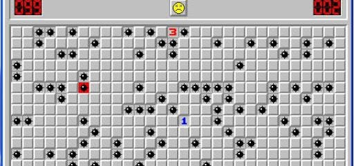
Figure 1 - Minesweeper of the Windows Operating System
Our project consists of a simple game with excellent dynamics, with the option of being played by two people.
Your main objective is to choose an empty square where there is no bomb. If there is a bomb in place, the game is over. Otherwise, the game continues. Based on this, each location will be represented by a button connected to the Arduino.
Therefore, in this article, you will learn the following concepts:
1. Develop the minefield game for Arduino;
2. Learn to use the random and randomseed function.
So, next, we will start the development of the minefield game with Arduino for you to have fun with your friends.
Minesweeper Game Development with Arduino
Based on this operating principle, the following circuit in Figure 1 was developed.
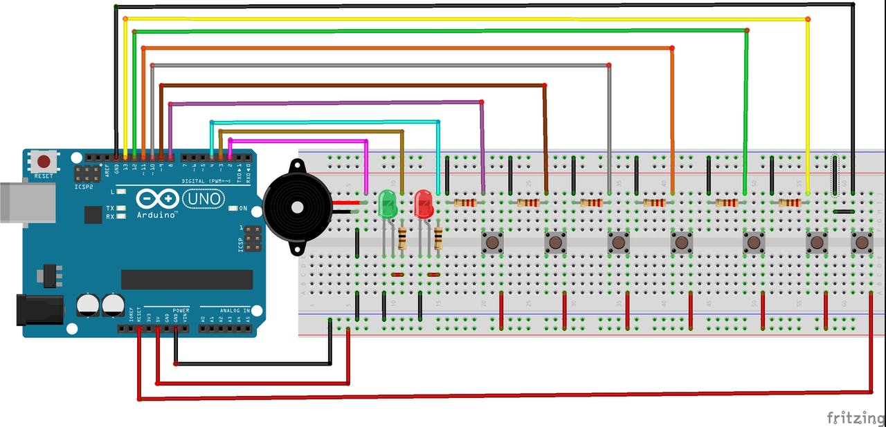
Figure 2 - Electronic Schematic in the Breadboard.
As we can see, this circuit is composed of an Arduino UNO, which is responsible for processing the logic of the game, buttons that simulate the locations, and the LEDs and buzzer, to indicate victory and defeat in the game through light and audible signals.
From now on we will cover the circuit's operation and the logic implemented in the circuit.
Minesweeper with Arduino
The main objective of the game is to find an empty space where there is no bomb. Otherwise, if the user presses the button where the pump is, the system will generate an alarm signaling that the user has lost the game.
For this, we will use buttons to simulate each square. We will use programming logic to draw the digital pin number of one of the buttons. After the draw, the mine will be assigned to this respective button.
In this way, we will now present the code of the developed project.
The code is shown below.
        int numero;
int estado;
int buzzer = 2;

void setup()
{
pinMode(2, OUTPUT);
pinMode(3, OUTPUT);
pinMode(buzzer,OUTPUT);
pinMode(8, INPUT);
pinMode(9, INPUT);
pinMode(10, INPUT);
pinMode(11, INPUT);
pinMode(12, INPUT);
pinMode(13, INPUT);
randomSeed(analogRead(A0));
numero = random(8,14);
}

void loop()
{
digitalWrite(3, HIGH);
estado = digitalRead(numero);
while(estado == 1)
{
digitalWrite(4, HIGH);
tone(buzzer,1500);
delay(100);
digitalWrite(3, LOW);
noTone(buzzer);
digitalWrite(4, LOW);
tone(buzzer,1500);
delay(100);
digitalWrite(3, HIGH);
noTone(buzzer);
delay(100);
while(estado == 0)
{
estado = 1;
}
}
}
As you can see, a variable was first declared for the digital pins connected to the buttons. In addition, we will create a variable to check the status of these buttons, that is, if they are in high or low logic state.
Finally, we declare a variable for the buzzer and assign a digital port to that variable.
        int numero; // Variável referente aos pinos digitais conectados aos botões //
int estado; // Variável para verificar o estado dos botôes, se estão em nivel lógico alto ou baixo. //
int buzzer = 2; // Váriavel atribuida ao pino digital 7, referente ao buzzer.//
Next, we have the setup function. In this function, we configure the I / O pins for connection of the buttons as input and the LED's and Buzzer pins as outputs.
In addition, we use the randomSeed function. This function uses as a parameter the value read on a disconnected analog input to generate a seed value. Because it is known that a disconnected analog pin will generate random values and, thus, we have a really random effect on the value generated in the code.
In addition to the randomseed function, we use the random function. This function returns numbers from an internal Arduino pre-established list. It is a huge list of scrambled numbers and will always be the same sequence of numbers, in fact it is not a random number.
When we restart the Arduino, it starts this sequence again.
For this project, we raffled a number within the range of 8-14. These values were chosen because they are the values of the digital pins that are connected to the buttons on the Arduino.
        void setup()
{
pinMode(2, OUTPUT);
pinMode(3, OUTPUT);
pinMode(buzzer,OUTPUT);
pinMode(8, INPUT);
pinMode(9, INPUT);
pinMode(10, INPUT);
pinMode(11, INPUT);
pinMode(12, INPUT);
pinMode(13, INPUT);
randomSeed(analogRead(A0));
numero = random(8,14);
}
Finally, we have the loop function. At its start, the green LED is activated to indicate that the game has started and that players can start the game. Then, the user must select a key, as shown in the circuit below.

Figure 3 - Starting the Minesweeper game.
When a selected switch does not have the pump in place, the green LED will remain on and the red LED will remain off. In addition, the buzzer will not be triggered. This can be seen in the Figure below.
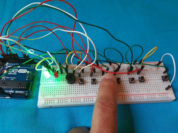
Figure 4 - Starting the Minesweeper game.
If the user selects a location and has a pump, the red LED will go on, the green LED will go off and the Buzzer will go on. This can be seen in the figure below.
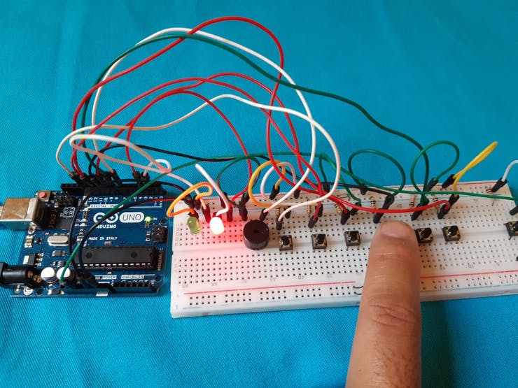
Figure 5 - Place with planted bomb.
Finally, we include a reset button, to restart the game the moment the pump is started. After pressing the button, the game restarts, the red LED is turned off and the green LED will be activated.
Then another random pin is drawn and your fun continues. This can be seen in Figure 5.
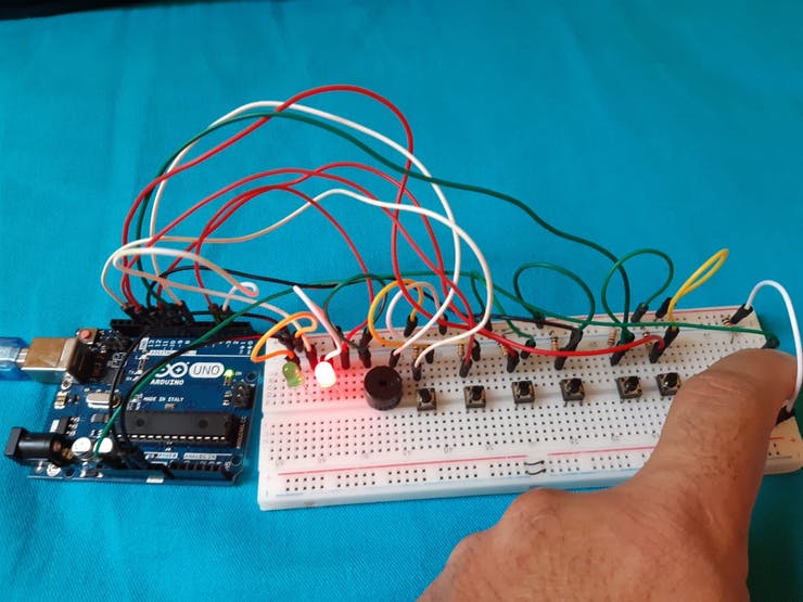

Figure 6 - Restarting the game.
Next, we will make the files available for you to mount this project on a NEXTPCB Printed Circuit Board. You can take advantage and purchase for free.
Printed Circuit Board NEXTPCB - Arduino Minesweeper
For this project, we decided to create a Shield for the Arduino UNO. On this board, there will be connected JST to connect the buttons, LEDs, and the buzzer.
In this way, we developed the electronic schematic design for the project. The schematic is shown in the following figure.

Figure 7 - Electronic Schematic of the Project.
The following schematic of the figure below was obtained from the electronic schematic. As you can see, we placed 10 JST connectors to connect the elements of the project.
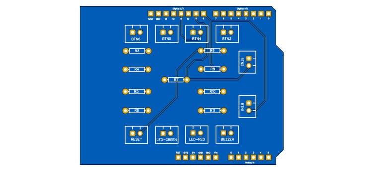
Figure 8 - 2D PCB Design.
You can now see the result of the project of the printed circuit board in the 3D view.

Figure 9 - 3D PCB Design.
With your NEXTPCB shield Arduino minesweeper you can set up your project and have fun with your friends.
Conclusion
Through the development of this game, we learned how to use one more of the several functions of Arduino and how to create an interactive project so that people can have fun.
This project is simple and can be set up at home with parents and children and in schools.
We appreciate the support of LOW COSTER PRINTED CIRCUIT BOARD - NEXTPCB COMPANY and follow our profile to receive new fun projects.
We all liked that feeling of nostalgia for the games and games we played in childhood and adolescence. Several consoles and computer games marked this era. One of the great games was the Minesweeper of the Windows Operating System, which is shown in Figure 1.
In this game, we aimed to select a location that did not have a bomb. Otherwise, we lost the game.
Therefore, it was thinking about the concept of this game, that we created this project with the objective of bringing back a game that is well known to all: the minefield.
Figure 1 - Minesweeper of the Windows Operating System
Our project consists of a simple game with excellent dynamics, with the option of being played by two people.
Your main objective is to choose an empty square where there is no bomb. If there is a bomb in place, the game is over. Otherwise, the game continues. Based on this, each location will be represented by a button connected to the Arduino.
Therefore, in this article, you will learn the following concepts:
1. Develop the minefield game for Arduino;
2. Learn to use the random and randomseed function.
So, next, we will start the development of the minefield game with Arduino for you to have fun with your friends.
Minesweeper Game Development with Arduino
Based on this operating principle, the following circuit in Figure 1 was developed.
Figure 2 - Electronic Schematic in the Breadboard.
As we can see, this circuit is composed of an Arduino UNO, which is responsible for processing the logic of the game, buttons that simulate the locations, and the LEDs and buzzer, to indicate victory and defeat in the game through light and audible signals.
From now on we will cover the circuit's operation and the logic implemented in the circuit.
Minesweeper with Arduino
The main objective of the game is to find an empty space where there is no bomb. Otherwise, if the user presses the button where the pump is, the system will generate an alarm signaling that the user has lost the game.
For this, we will use buttons to simulate each square. We will use programming logic to draw the digital pin number of one of the buttons. After the draw, the mine will be assigned to this respective button.
In this way, we will now present the code of the developed project.
The code is shown below.
        int numero;
int estado;
int buzzer = 2;

void setup()
{
pinMode(2, OUTPUT);
pinMode(3, OUTPUT);
pinMode(buzzer,OUTPUT);
pinMode(8, INPUT);
pinMode(9, INPUT);
pinMode(10, INPUT);
pinMode(11, INPUT);
pinMode(12, INPUT);
pinMode(13, INPUT);
randomSeed(analogRead(A0));
numero = random(8,14);
}

void loop()
{
digitalWrite(3, HIGH);
estado = digitalRead(numero);
while(estado == 1)
{
digitalWrite(4, HIGH);
tone(buzzer,1500);
delay(100);
digitalWrite(3, LOW);
noTone(buzzer);
digitalWrite(4, LOW);
tone(buzzer,1500);
delay(100);
digitalWrite(3, HIGH);
noTone(buzzer);
delay(100);
while(estado == 0)
{
estado = 1;
}
}
}
As you can see, a variable was first declared for the digital pins connected to the buttons. In addition, we will create a variable to check the status of these buttons, that is, if they are in high or low logic state.
Finally, we declare a variable for the buzzer and assign a digital port to that variable.
        int numero; // Variável referente aos pinos digitais conectados aos botões //
int estado; // Variável para verificar o estado dos botôes, se estão em nivel lógico alto ou baixo. //
int buzzer = 2; // Váriavel atribuida ao pino digital 7, referente ao buzzer.//
Next, we have the setup function. In this function, we configure the I / O pins for connection of the buttons as input and the LED's and Buzzer pins as outputs.
In addition, we use the randomSeed function. This function uses as a parameter the value read on a disconnected analog input to generate a seed value. Because it is known that a disconnected analog pin will generate random values and, thus, we have a really random effect on the value generated in the code.
In addition to the randomseed function, we use the random function. This function returns numbers from an internal Arduino pre-established list. It is a huge list of scrambled numbers and will always be the same sequence of numbers, in fact it is not a random number.
When we restart the Arduino, it starts this sequence again.
For this project, we raffled a number within the range of 8-14. These values were chosen because they are the values of the digital pins that are connected to the buttons on the Arduino.
        void setup()
{
pinMode(2, OUTPUT);
pinMode(3, OUTPUT);
pinMode(buzzer,OUTPUT);
pinMode(8, INPUT);
pinMode(9, INPUT);
pinMode(10, INPUT);
pinMode(11, INPUT);
pinMode(12, INPUT);
pinMode(13, INPUT);
randomSeed(analogRead(A0));
numero = random(8,14);
}
Finally, we have the loop function. At its start, the green LED is activated to indicate that the game has started and that players can start the game. Then, the user must select a key, as shown in the circuit below.
Figure 3 - Starting the Minesweeper game.
When a selected switch does not have the pump in place, the green LED will remain on and the red LED will remain off. In addition, the buzzer will not be triggered. This can be seen in the Figure below.
Figure 4 - Starting the Minesweeper game.
If the user selects a location and has a pump, the red LED will go on, the green LED will go off and the Buzzer will go on. This can be seen in the figure below.
Figure 5 - Place with planted bomb.
Finally, we include a reset button, to restart the game the moment the pump is started. After pressing the button, the game restarts, the red LED is turned off and the green LED will be activated.
Then another random pin is drawn and your fun continues. This can be seen in Figure 5.
Figure 6 - Restarting the game.
Next, we will make the files available for you to mount this project on a NEXTPCB Printed Circuit Board. You can take advantage and purchase for free.
Printed Circuit Board NEXTPCB - Arduino Minesweeper
For this project, we decided to create a Shield for the Arduino UNO. On this board, there will be connected JST to connect the buttons, LEDs, and the buzzer.
In this way, we developed the electronic schematic design for the project. The schematic is shown in the following figure.
Figure 7 - Electronic Schematic of the Project.
The following schematic of the figure below was obtained from the electronic schematic. As you can see, we placed 10 JST connectors to connect the elements of the project.
Figure 8 - 2D PCB Design.
You can now see the result of the project of the printed circuit board in the 3D view.
Figure 9 - 3D PCB Design.
With your NEXTPCB shield Arduino minesweeper you can set up your project and have fun with your friends.
Conclusion
Through the development of this game, we learned how to use one more of the several functions of Arduino and how to create an interactive project so that people can have fun.
This project is simple and can be set up at home with parents and children and in schools.
We appreciate the support of LOW COSTER PRINTED CIRCUIT BOARD - NEXTPCB COMPANY and follow our profile to receive new fun projects.