The project of the low pass filter RC
The low pass filter is excellent electronic circuits to filter out parasitic signals from your projects. A common problem in projects with Arduino and systems with sensors working close to power circuits is the presence of “parasitic” signals.
They can be caused by vibration or magnetic fields in the same area as the sensor.
These signals, which are mostly of high frequency, cause disturbance at the time of reading and, consequently, erroneous readings occur in the automation system. A common example is the starting of a machine that requires a high initial current.
This will cause the generation of high-frequency noise in several elements that are connected to the electrical network, including sensors.
To prevent these noises from affecting the system, filters are used between the sensor element and the system that reads it.
What are passive and active filters?
What are passive and active filters?
Filters are circuits that can “clean” a signal, separate unwanted signals, to avoid reading values that do not match reality.
Filters can be of two types: passive and active.
Passive Filters
Filters can be passive, which are the simplest, as they consist only of resistors and capacitors.
Active Filters
Active filters, in addition to resistors and capacitors, use amp-ops to improve filtering, and digital filters, which are used in processors and microcontrollers.
Therefore, in this article, you will learn:
- Understand how low pass filter work;
- Configure the hardware of the low pass filter with a cutoff frequency of 100 Hz using an operational amplifier LM358;
- Calculate the values of the passive components of the circuit;
- Assemble a low pass filter NextPCB.
Below, we present the process of developing the active low pass filter for our circuits with Arduino.
Development of the active low pass filter RC circuit
In this project an active low pass filter will be developed with NEXTPCB - Printed Circuit Board, that is, it allows us to pass low frequencies. The frequency range to be chosen depends on the operation of the circuit.
For this article we will use an active low pass filter, as they are used for frequencies below 1MHz, and, in addition, signal amplification can be done, as an operational amplifier will be used in this circuit.
Therefore, based on this project, the central focus will be on the development of the active low pass filter circuit and its symmetrical supply circuit. Figure 1 illustrates the hardware of this circuit.
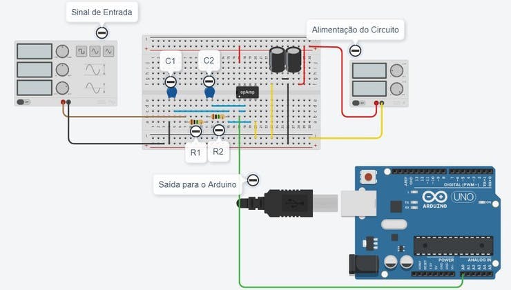
Figure 1 - Low Pass Filter RC circuit constructed in TinkerCAD.
The low pass filter RC circuit constructed in TinkerCAD can be accessed at the following link: https://www.tinkercad.com/things/0H8Wq5NJLm0-filtro-ativo
As mentioned, we used Arduino in this project in order to acquire the signal from a sensor. Thus, the low pass filter RC circuit in the figure above we have 3 important parts:
- The signal generator,
- The active filter and;
- Arduino for collecting sensor data.
The signal generator is responsible for simulating the functioning of a sensor and transmitting the signal to the Arduino. This signal is then filtered through the low pass filter RC and, subsequently, the filtered signal is read and processed by Arduino.
Thus, to perform the assembly of the low pass filter RC we will need the following electronic components:
- 2 Resistors;
- 2 ceramic capacitors;
- 2 Electrolytic capacitors;
- Operational Amplifier LM358;
- Power terminals or 9V battery;
Next, we present the calculation of the values of the resistors and capacitors of the circuit. The calculation of these components is based on the low pass filter cutoff frequency of the active filter.
Resistor and Capacitor Calculations
For the proposed circuit, we will use a low pass filter cutoff frequency of 100Hz. In this way, the circuit will allow frequencies to pass below 100Hz and above 100Hz, the signal will...
Read more »
 Jesse
Jesse
 Sagar 001
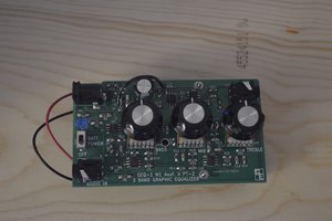
 Grant Giesbrecht