 Silícios Lab
According to information from the official Instagram of the Arduino company, there are approximately 30 million active users of the platform. All of them are spread all over the world.
With this large number, we realize how much the platform has great influence and use by many people.
One of the factors driving the platform's rapid growth is why it is open-source and open-hardware, meaning anyone can create their own Arduino.
Thus, with a wide variety of boards in the world market, Arduino has become popular and continues to reach more and more people daily.
With this possibility of creating new cards, we present the Mini USB Arduino. It is a small Arduino, which was developed using an ATtiny85 chip.
For this project you'll need:
- 01 x PCBWay Custom PCB
- 02 x 1N4729 Zener Diode - UTSOURCE
- 02 x 68R Resistor - UTSOURCE
- 01 x 1k5R Resistor - UTSOURCE
- 01 x 100nF Capacitor Electrolytic - UTSOURCE
- 01 x LED 5mm - UTSOURCE
- 01 x Eletrolytic Capacitor 10nF - UTSOURCE
- 01 x Header Pin - UTSOURCE
- 01 x 1kR Resistor - UTSOURCE
- 01 x 1N4148 Diode - UTSOURCE
- 01 x Attiny85 Microcontroller - UTSOURCE
In this article, we will release the downloadable files and leave them in our PCBWay repository.
The Mini USB Arduino
The Arduino Mini USB is designed to be a small, compact-size Arduino using the ATtiny85 microcontroller as shown in Figure 1.
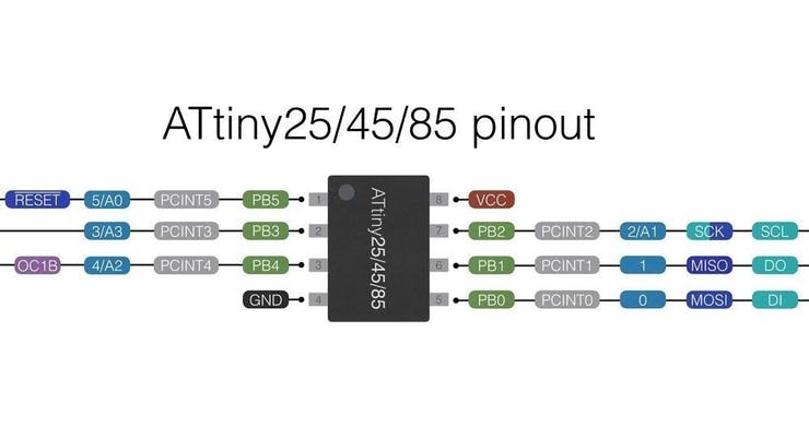
Figure 1 - Attiny85 Electronic Schematic Pinout.
Its purpose is to make programming easier, avoid the use of recording cable, and be small in size. applied to projects that require a small control circuit.
The ATtiny85 microcontroller can be programmed directly through the computer's USB. Hereby we place a USB connector directly on the printed circuit board.
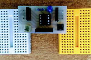
This will make recording easier and will prevent users from using cables. In Figure 2 we present the Arduino Mini USB PCB.
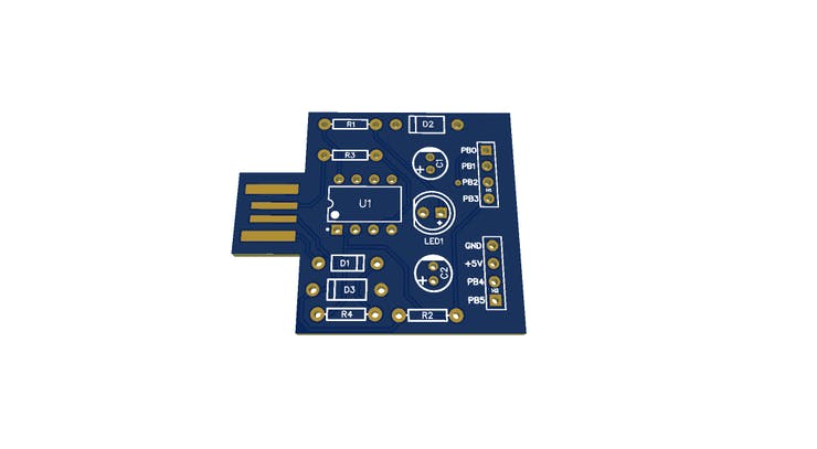
Figure 2 - Mini USB Arduino Compatible.
As is possible to see in Figure 2, the board was developed with as mall size and with the connector in your own structure.
Now, you'll present the electronic schematic and offer the project files of the board.
Electronic Schematic of Mini USB Arduino
In Figure 3 is presented the electronic schematic of the Mini USB Arduino. As is possible to see, the project has a USB connector to flash the ATtiny85 microcontroller.

Figure 3 - Electronic Schematic of the Printed Circuit Board.
In addition, it has LED to signalize the power on the circuit and connector to connect external circuits.
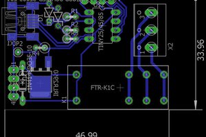
After the electronic schematic, was designed the project of the Mini USB Arduino. The result is shown in Figure 4.
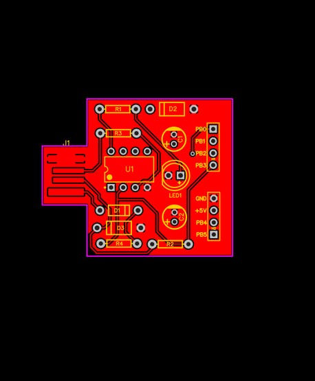
Figure 4 - Mini USB Arduino Board PCB Design.
The Arduino Mini USB Board is designed to be easily assembled and has all PTH-shaped electronic components, ie, through these components, there is greater ease of welding on the board.
In addition, the PCB already has a USB connector, which can be plugged directly into the computer's USB and write code without the need to use recording cables.
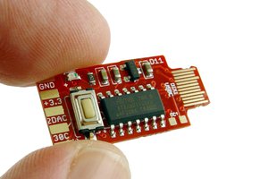
Finally, we present the result of the developed circuit board in Figure 5.

Figure 6 - Mini USB Arduino Compatible Printed Circuit Board.
Acknowldgement
The Silícios Lab thanks to the PCBWay for the support and you for reading all articles.
Thanks too UTSOURCE to offer the electronic components to construct the project.

 bobricius
Reminds me of a digispark!
https://s3.amazonaws.com/digistump-resources/files/97a1bb28_DigisparkSchematic.pdf