 Bharbour
The design for the RS232 to CI-V adapter was shamelessly copied from https://www.qsl.net/g3vgr/civ.html, thanks!
ICOM calls their communication system CI-V and Yeasu calls it CAT. The name CAT seems to be in wider usage for this purpose. Both interfaces use a similar physical layer design.
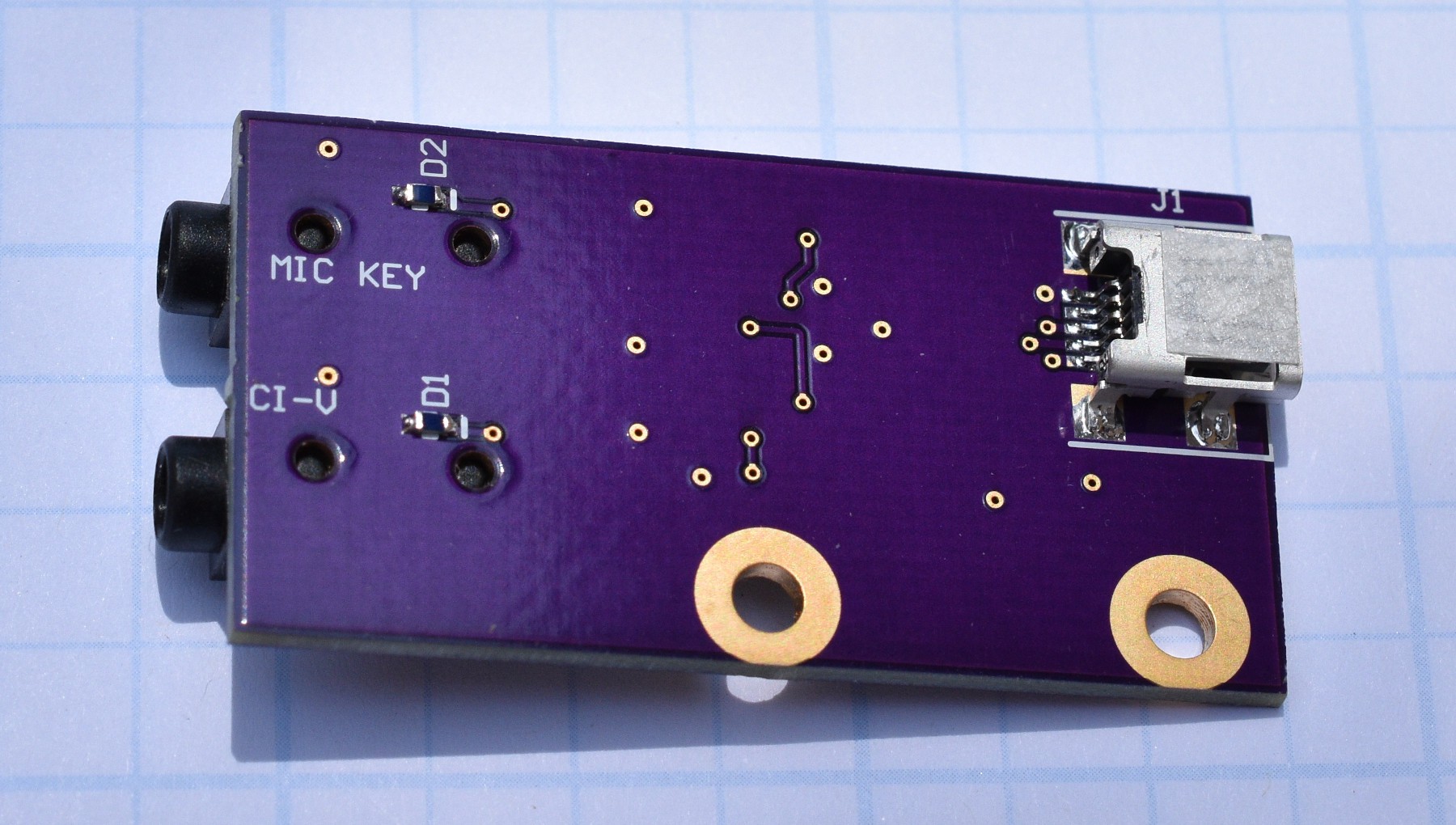
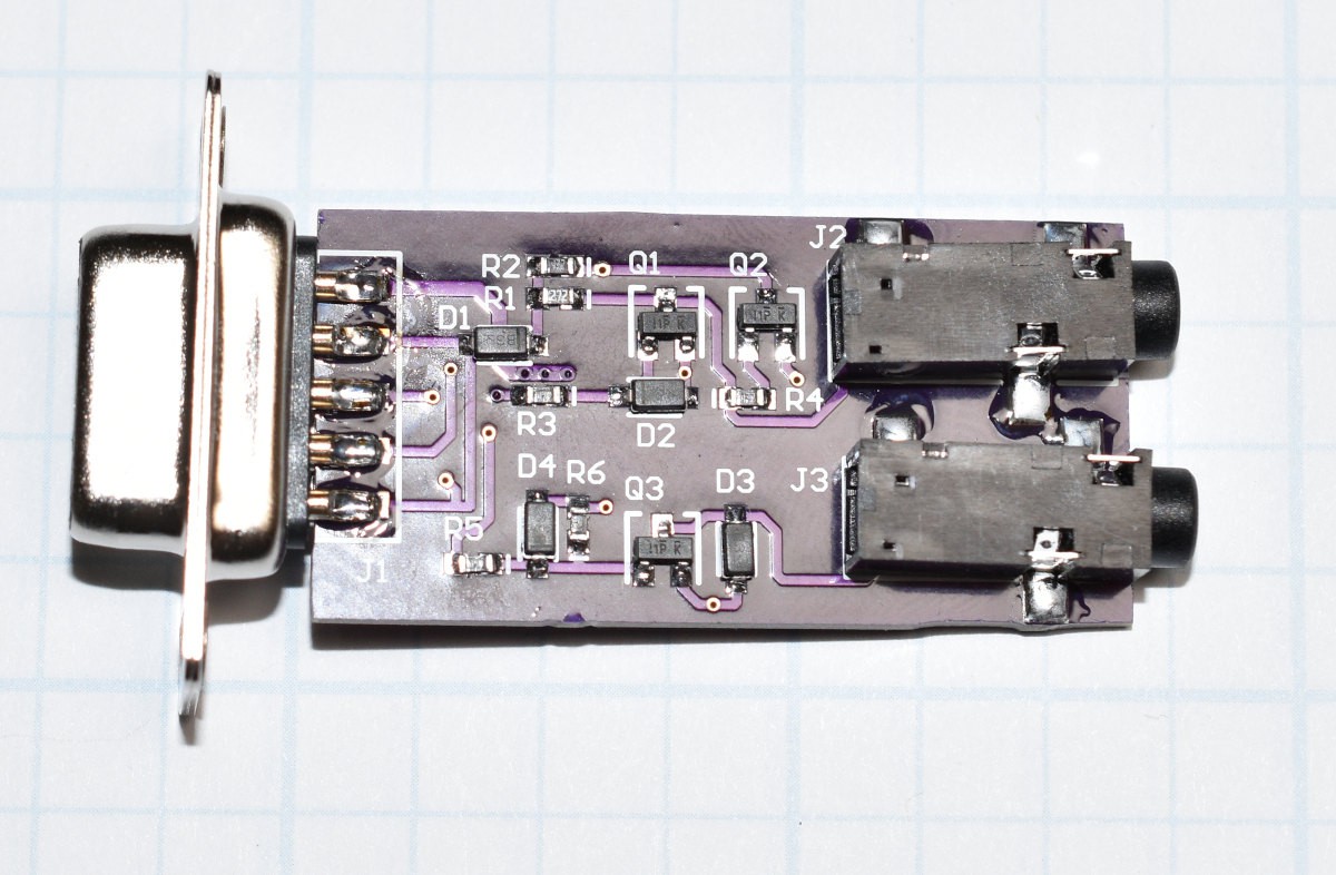
Looking at the schematic for the 9 Pin RS232 to CAT / CI-V interface, you can see that the board is powered from pin 4 (DTR) , so DTR must be set high for the board to operate. The diode D1 is used to prevent the positive power supply from going negative if the DTR signal goes low. The normal output voltage range for current USB to RS232 adaptors seems to be about -6V to +6V. The TXD signal (pin 3) drives an NPN transistor (Q1) to get the "open collector" aspect of the output side of the bus. It also logically inverts the RS232 levels before applying them to the COM_IO signal to the radio. D2 prevents the TXD signal from driving the base of Q1 below ground. The COM_IO signal is pulled up to about 5V by the voltage supplied by the DTR pin. When the host is not actively talking to the radio, the COM IO signal idles in the high state. Responses from the radio go through Q2 to be inverted. Q2's output is also pulled up to about +5V and the resulting signal goes to the RXD pin on the 9 pin connector. The RXD signal never goes negative like a real RS232 signal, but it works as is. The DTR signal (pin 4) on the 9 pin connector is also used to pull up the DSR (pin 6) and DCD (pin 1) on the D connector. The RTS signal (pin 7) is also driving the CTS input (pin 8). These extra handshake signal connections may help keep the UART happy but are probably not necessary.
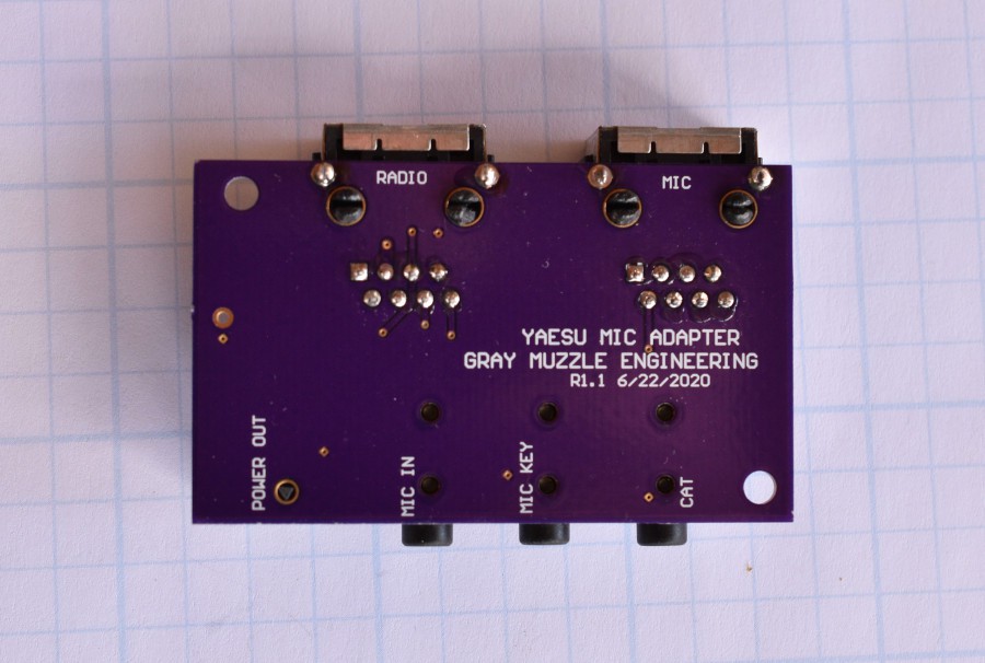
The operation of the MIC-KEY is similar, the RTS signal (pin 7) drives the base of another NPN transistor (Q3) to pull the MIC-KEY signal to ground when the RTS pin goes high. DIODE D4 prevents the base of Q3 from being pulled below ground. Diode D3 prevents the MIC-KEY signal on the collector of Q3 from being pulled below ground. This logical convention works with existing software (WSJT-X), so it is apparently standard. One thing to be aware of is that some radios use considerably higher voltage for keying the microphone, so a relay should be used to drive such a radio.
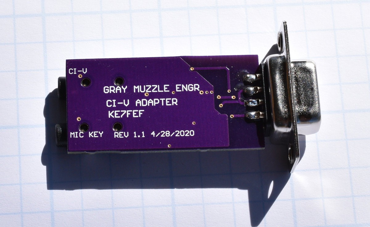
Both of the output connectors are just 3.5mm stereo sockets. The tip and the sleeve are used. The first rev PCB that I did had the tip and ring pins interchanged, hence the blue wires. Rev 1.1 of the boards have already been sent out to OSHPark. The ICOM radio that I am testing with has a 3.5mm connector for the CI-V signal, making the cable simple. Yaesu and Kenwood use mini-DIN connectors, so a different cable will have to be made to drive one of these radios.
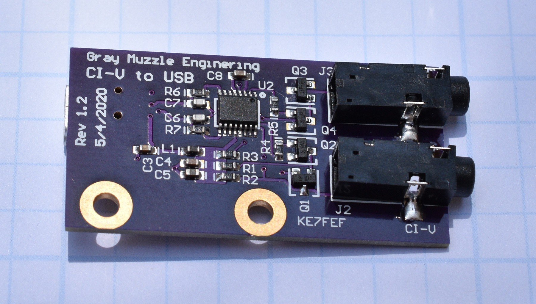
The USB to CAT / CI-V adapter is my own design and uses an FT230X UART chip to go from USB to logic level UART signals. Both of the output signals have a second grounded emitter transistor to provide a second inversion. The logic level to RS232 level shifter chips in a normal serial port perform an inversion on each signal, so this second inversion is necesary to keep the logical sense of the COM_IO signal the same as the RS232 version of the adapter. The USB VBUS power (about 5V) is used to pull up the signals in the output section.


 marble
 Bruce Land
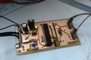
 yangosoft
I too have been exploring the use of the CI-V interface. My original goal. was to create a 'simple' mechanism to add external buttons to my transceiver ( IC 7300 ). Essentially that job's done (switching modes is now a dream), but there are some other things I can do e.g. get the S-meter value, VCO frequency, and mode info over the CI-V interface and display those on external devices. The original rat's nest was built around an Arduino 2560 Mega, but I've kept the code small and have put an Arduino pro mini on the CI-V interface p.c.b. Now pondering what to do next.
https://youtu.be/urFd8D0IUtM