 Bharbour
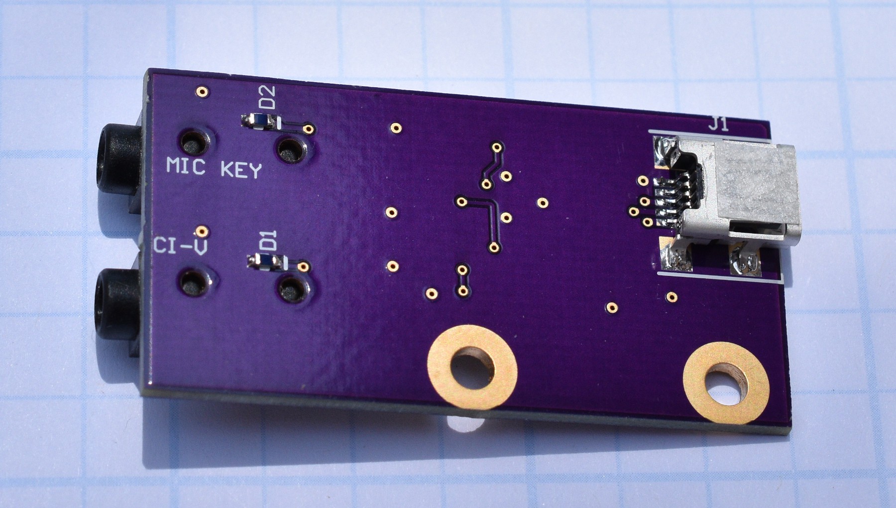
The revised PCBs for both the RS232 to CI-V and the USB to CI-V units came in on Friday. Revision 1.1 of the USB board just had the wiring error fixed and never got sent to fabrication. Revision 1.2 is rip up and re-do on the component placement from revision 1.0 of on the USB board. On the initial PCB, the USB data + and - lines had to cross between the connector and the chip. Orientation of the chip did not work well with either the USB connections. The two 3.5mm jacks were close enough together that it was marginal to plug both in simultaneously. On Rev 1.2, the USB connector got moved to the back side of the board and the chip got rotated 90 degrees. Spacing between the 3.5mm jacks got increased. The rest of the components got re-distributed to work with those changes. Board size remained the same. The wiring error on the 3.5mm jack got corrected as well. I am not a big fan of connectors on the back side of a PCB, but it was the best choice with the connectors that I have. The new layout is much cleaner. Building the Rev 1.2 board went quickly, even with hand soldering the SMT USB connector to the back side of the board.
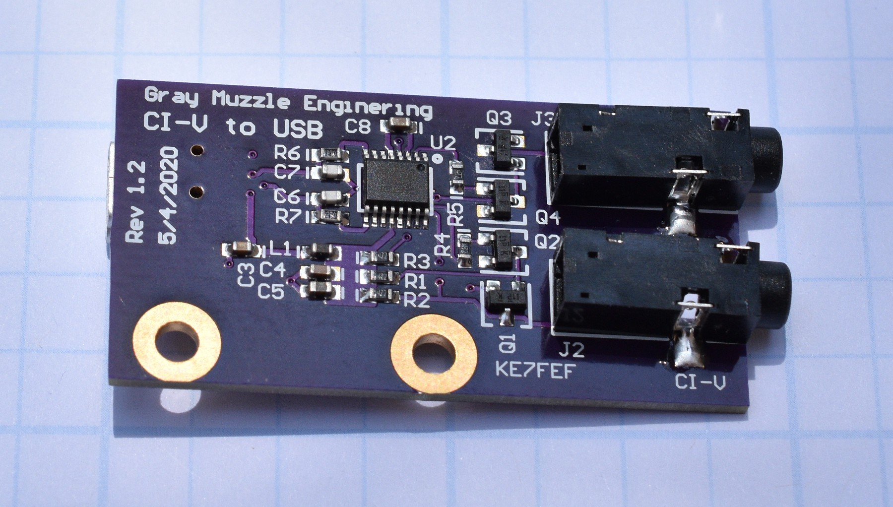
I swapped the Rev 1.2 board for the 1.0 board on my FT8 setup this morning and it works fine.
If anybody is interested in building one (or 3) of these boards, message me and I will send you the artwork. If people are interested, I will share the artwork on OSH Park. A run of 3 boards costs about $9.60US and the components to populate a board are about $10US for one board.
I was planning to wait to build the revision 1.1 of the RS232 board, but the externally powered version PCBs will not be here until late this week and I got bored.
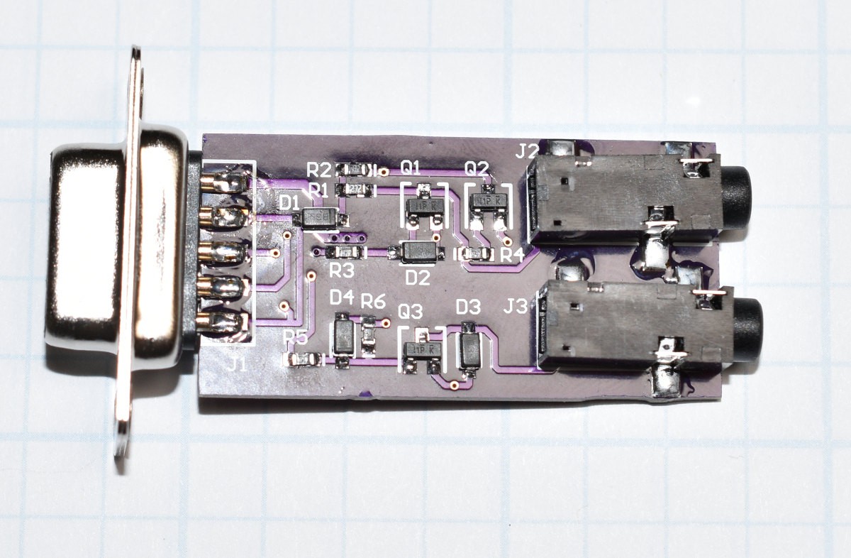
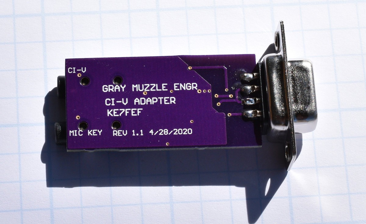
The only changes on the 1.1 version are to fix the wiring error and add keying holes to the 3.5mm jacks. The new boards built up and work fine.
Discussions
Become a Hackaday.io Member
Create an account to leave a comment. Already have an account? Log In.