 rik keenes
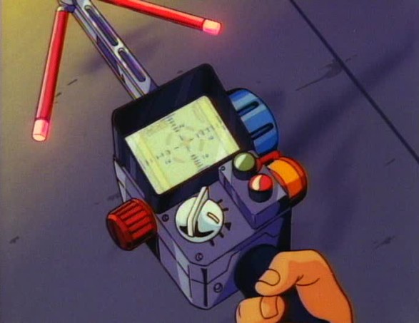
There was one cartoon in particular that seems to dominate my childhood memories and that was The Real Ghostbusters. Ray, Winston, Peter and Egon were armed to the teeth with really cool gadgets, among them the PKE meter. This was my favourite of all their tech and it basically detected the ghosts they were trying to hunt.
What I am going to do is make my own fully functional PKE meter.
Things you'll need:
- 3D printer
- 3D model files (found here)
- Raspberry Pi 3B+
- Pi night vision camera
- Sense Hat
- 3.5" Monitor (I've found a cheap alternative to the usual screens you can get, find it here)
- Wires
- Screws/bolts
- Battery pack
- Buttons (I used some left over from an arcade project)
- A word library
Printing The Case
The 3D model I used is printed off in parts, most of the smaller bits I didn't even print off. I am only using the handle, the main box, the lid which houses the buttons and screen and also part of the antenna.
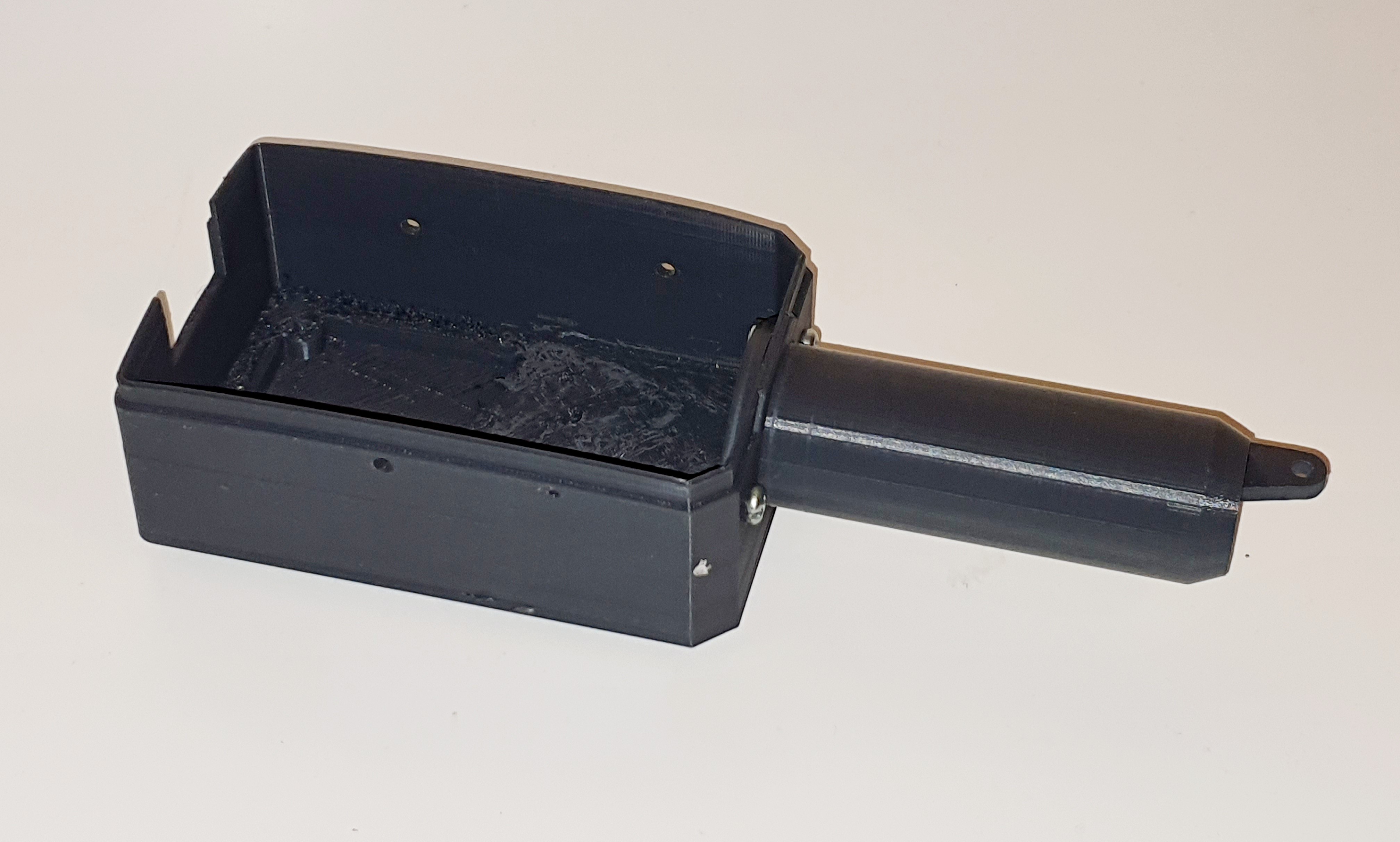
The 3D print originally intends the use of little arms coming out of either side of the main antenna but I have decided to attach a night vision camera to mine so that I can see in pitch black whilst using the PKE meter.
To attach the handle to the main box I used two nuts and bolts, pretty thick ones. This is better than using super glue in case you need to take it apart again. For the time being leave the top part off the box, we still need to fit the monitor.
Preparing The Monitor
I have searched the internet high and low but couldn't find a suitable screen which would fit the 3D print. That's when I resorted to looking for RCA composite screens.
There's a lot of screens on Amazon designed to be used with car reversing cameras. These types of cameras are the perfect dimensions for this project and they only cost around £15. This is less than half the price of normal LCD's designed to be used with the Raspberry Pi. They require some modding before it can be used with the Pi.

The quality of the screens isn’t as good as an LCD but it gives that retro effect that I think fits perfectly with this project.
The monitor is designed to be used in a car with a rear view reversing camera. We won’t be needing any of the wires or the case.
There are four screws securing the case, one of which will most likely be under the warranty sticker on the back. Just poke the screwdriver through to get to the screw. Once you have removed all four screws then the cover should become loose. Open it and carefully remove the screen assembly from the case. You will need to cut the wire just above the point it enters the outer case to remove it.
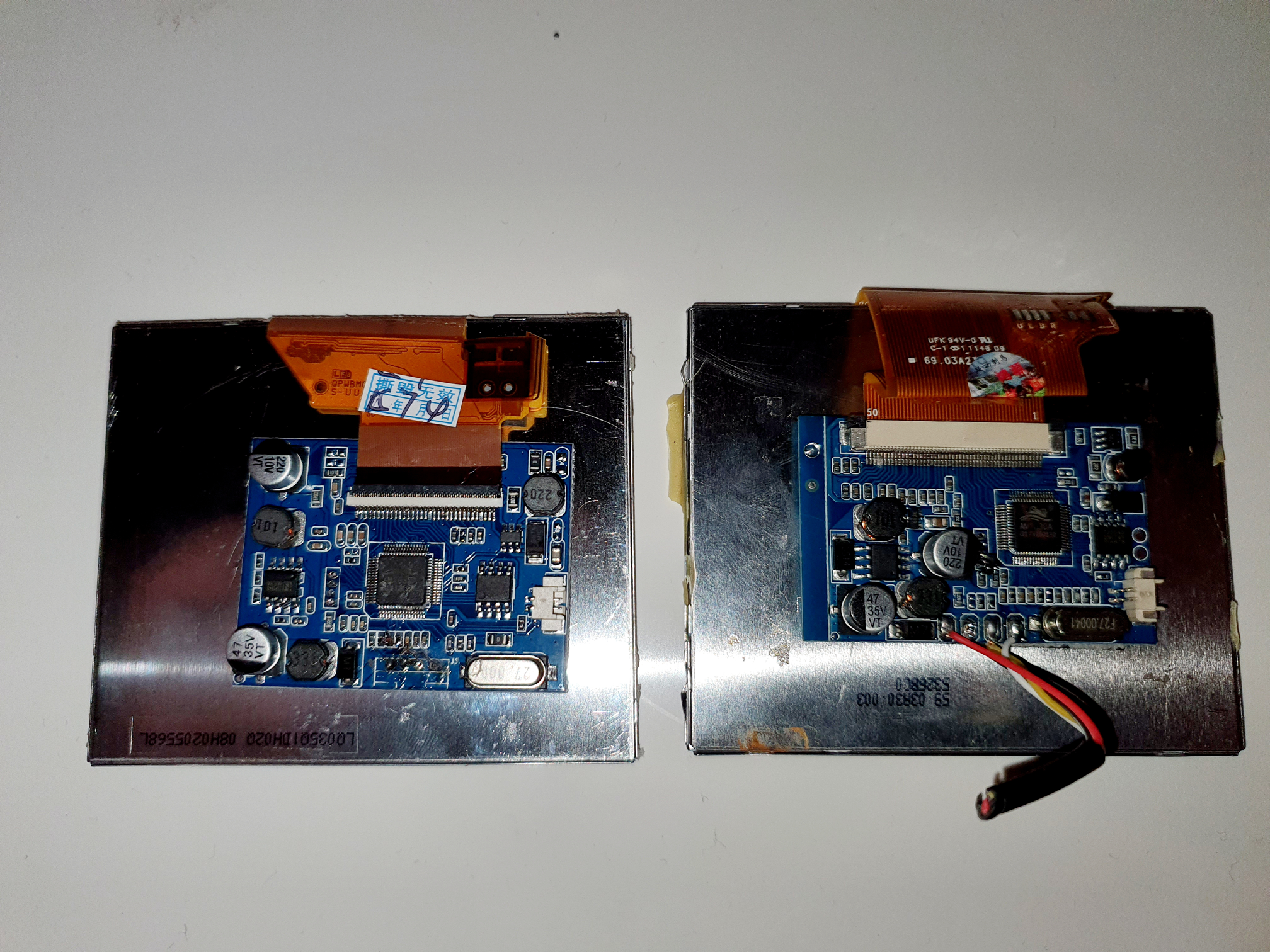
Once this is done you can work on the pcb more easily. Use a soldering iron to neatly remove all the wires. Once this is done you should have a screen with the pcb on the back.
As you can see below, the design of the pcb can vary as I’ve ordered a couple of these now (through trial and error damage!. These are the two variants I’ve come across so far and the orientation of some of the components differ from one to another.
First things first you need to solder a wire between one of the legs on the chip circled in the picture below to the left most contact at the bottom of the pcb.
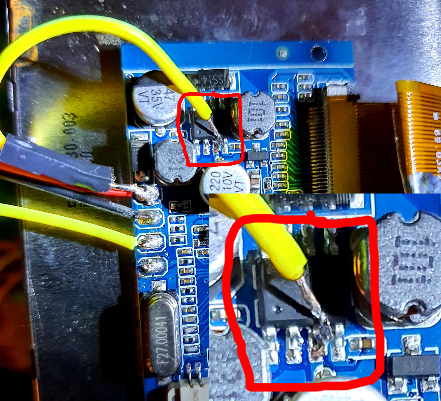
The contact that you just soldered the chip to is also being soldered from the same contact to one of the free 5V GPIO pins on the Pi. The black wire on the second contact connects to one of the free ground GPIO pins and the yellow wire on the third contact is being soldered to one of the contacts under the RCA jack underneath the Pi as pictured below.

Now your screen should register the Pi's output when you turn it on.
PLEASE STAY TUNED FOR MORE UPDATES
 jdelbe
 CompuCat
 Grégory Paul
 brian corteil