Close
0%
0%

Aerodox

[WIP] Keyboard based on Ergodox. But wireless?

Similar projects worth following
Update [2022-01-04]: based on much prior work by others, Aerodox is now a bluetooth, multi-PC keeb!

Somehow, I have between 4 and 5 computers on my desk that I need to switch between. Not all of them, not all the time. But enough that I think I need to address the fact that only one of them has a keyboard that I like, and that's a Surface Pro type pad. Some might not count that as a keyboard at all. Kristina Panos' general enthusiasm for human machine interfaces has rubbed off from her various recent articles and her Ergodox build is what made me decide to build my own keyboard. Or keeb. Or kbd.

Aims.
(1) make a mechanical keyboard that I can use for all my machines (obviously).
(2) make it wireless (because it might help with 1).

Please don't copy me as I'm going to make lots of mistakes.

I didn't know anything about mechanical keyboards other than proper computer people use them and they make lots of noise. The first thing I did was harangue @kristina panos about her Ergodox build and she graciously posted lots of images and set up a project in response.

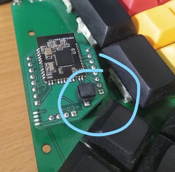
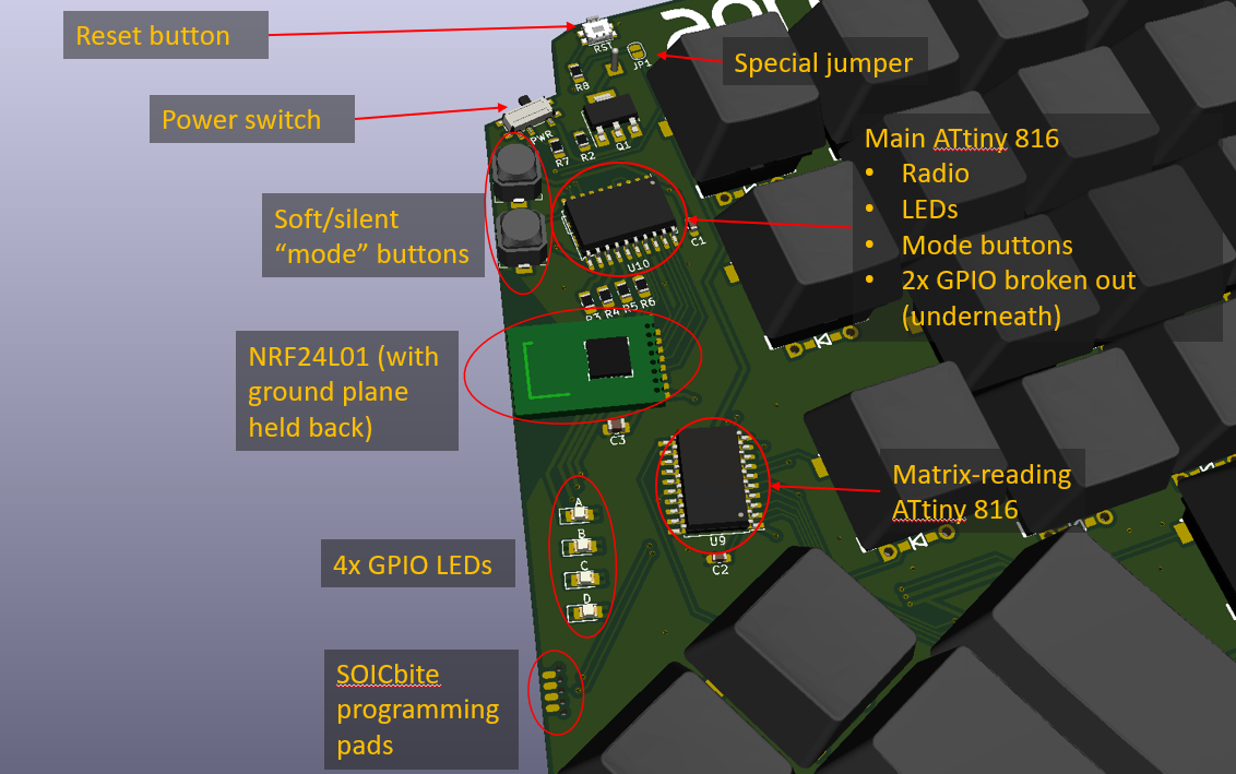
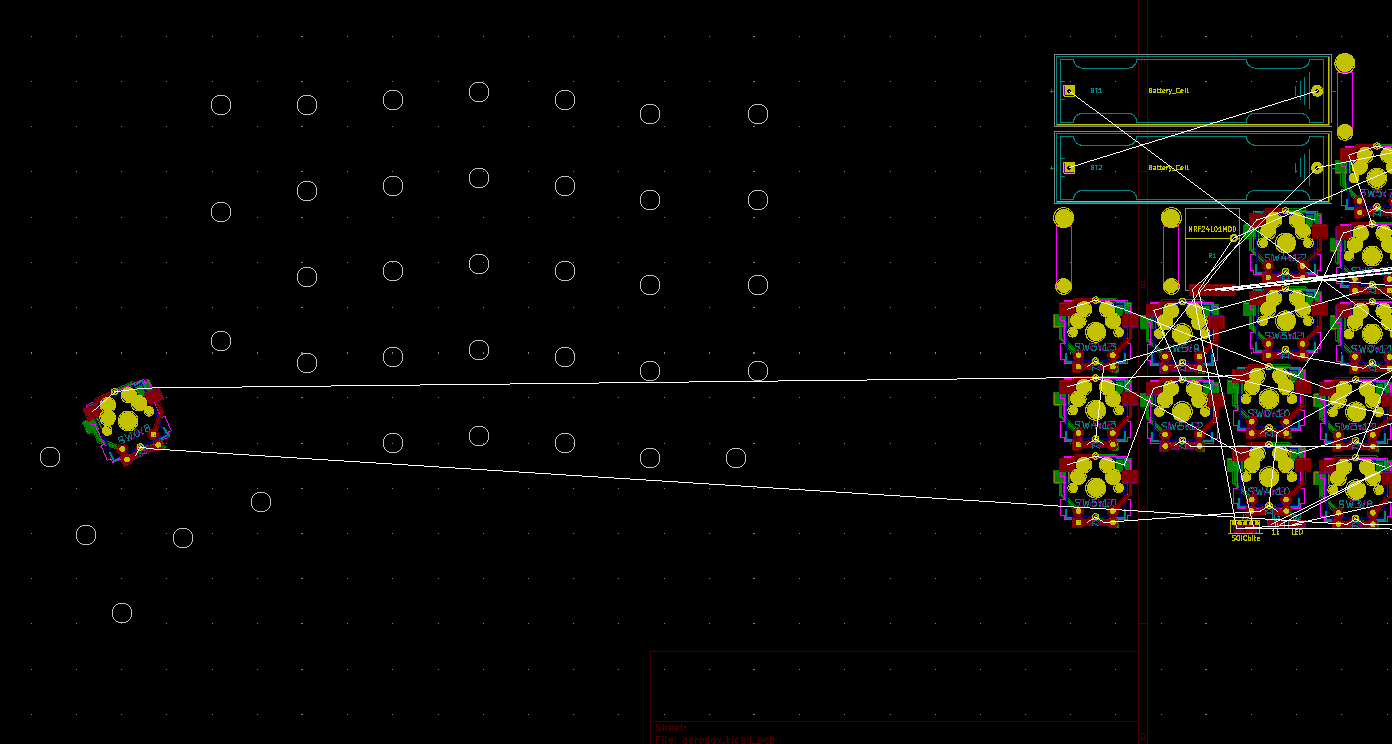
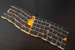
I looked at the Ergodox website and was delighted to find kicad files for the PCBs. I'm having a play with them at the moment. The "make it wireless" bit may be a pain to start with but I'm hopeful it will make the switching between computers simpler. The implications are that the keyboard halves will be battery powered (thinking 2x AA at the moment) and the second order implication is that the wireless comms will have to be very low power. I have dallied with IR comms before and come away thinking the resultant power is unlikely to beat NRF24L01 radio modules during normal use. And those radios are now so easy to get up and running.

Security is something to think about. Most people are worried about integrity in their RF projects - ie the receiver can trust that the message it receives originated from the true sender and hasn't been tampered with en-route. I also need to think about confidentiality, so that e.g. passwords can't be intercepted. The only thing I know about security is "don't roll your own crypto". 

I am minded to use a pair of microcontrollers - one in a matrix scanning role and the other in "everything else" mode, such as controlling the radio. If I get sleep and interrupts right, this may compare well with 1 microcontroller and 1 port expander that is the traditional approach. I haven't thought this through properly yet, but I'd love it if a microcontroller on the PC side with a standard QMK firmware running was attached to another microcontroller that was connected to the receiver radio and purely emulated the MCP23018 that's used in a standard Ergodox. That would make my firmware setup simpler and I hopefully won't have to get too far under the hood of QMK or roll my own HID code.

aerodox_schematic_r0-1.pdf

Just for interest. I'm sure plenty will need changing before it works.

Adobe Portable Document Format - 74.86 kB - 05/12/2020 at 21:04

Preview
Download

  • Look mum, no Pro Micro

    Simon Merrett01/04/2022 at 22:39 0 comments

    I'm pleased to say that, albeit not perfectly implemented, I have managed to turn #Aerodox into the project it was always supposed to be by getting it to work on more than one PC.  #Aerodox 's layout is based on Ergodox but it's circuitry is based on the #Redox keyboard 's wireless version. This was deliberately because Mattia Dal Ben had done a great job implementing a wireless keyboard and also documenting it. The internals of the wireless Redox were a clear analogue that showed me what I wanted probably lay down that path. 

    Unfortunately, it would need a receiver on each PC, as well as a Gazell protocol channel hopping scheme that you would need to switch over on both halves of the keyboard. After making the changes to boost the voltage on the motherboards, I was using Aerodox daily and knew I wanted to make a move to use it on my other PC(s). But one thing was niggling me - someone had managed to get bluetooth working on the Mitosis, the keyboard that I think inspired the Redox wireless and they now had a small keyboard that had a Gazell link between the halves and bluetooth from one half back to the PC. 

    The icing on the cake for me was that they were able to switch between 3 different PCs using the bluetooth. For the last two days I have been trying adapt the Bluetosis code to work on #Aerodox and tonight I finally got it working. I'm so chuffed I can switch between my two main PCs with a press of this little button:

    There are kinks to iron out. Firstly, I had to ditch the way timer interrupts and debouncing is done in the Redox way and I think I have taken a hit on responsiveness to key presses on the right (bluetooth/Gazell host) half. But I'm optimistic that I'll be able to tweak that. For example, there is an 8Hz Gazell message transmission that the left half sends until it goes to sleep after 500ms and I think the new scheme could potentially do away with that, freeing up buffer-transfers on the host side.

    Other things that other people may not like is that although the keymaps are qmk-like, nothing is running qmk any more (it was on the pro-micro connected to / built into the Redox wireless receiver). I don't care as I can press all the keys I want to!

    Other than optimising the responsiveness, what else is there to do with Aerodox? Well this recent foray has given me more confidence to navigate Nordic chips and tools, and with ZMK up-and-coming, perhaps we'll see an NRF52 version of #Aerodox one day. 

    Also, you can't go your whole life wondering if the first split ortholinear ergo key layout you picked was the best one, when there are so many to try...

  • Aerodox gets boosted

    Simon Merrett01/04/2022 at 22:13 0 comments

    Well, this is overdue and short. But one of the biggest failings of Aerodox was an extremely poor range to the PC, needing to press a key several times before it would register and sometimes pressing the key resulted in multiple keystrokes on screen.

    A long and winding thread at github where we got distracted by Gazell channel hopping configuration settings ended in me testing the difference between a solid 3.3V supply and the 2x AA cells I was using. Bear in mind the "spec" for the NRF51822 modules we're using says they go down to 2V. The difference was night and day.

    The nice thing about making #Aerodox modular is that all I needed to do was add a boost converter on a new motherboard (daughterboard?) PCB. The results were great, at low cost. I had to remove the space I had left for a second button but since I don't use the buttons for anything, it wasn't a hardship. 


  • Split test

    Simon Merrett08/15/2020 at 08:58 0 comments

    This log is well overdue but I honestly hadn't made any progress until yesterday. All the parts were here but the firmware was putting me off starting the hardware.

    Hardware 

    Apart from the opportunity for a pun, I thought I would see how long the diodes and hot-swappable switch holders would take to solder (a) with solder paste dispensed by hand and then the board reflowed and (b) soldering by hand. The solder paste, place and reflow method took me 25 minutes and the hand soldering of exactly the same components on the other half of the keyboard took me 35 minutes. That might not be interesting to you but I have often wondered where the threshold of hand soldering even SMT parts is compared to splodging some solder paste down from a syringe and plopping the parts on top. For clarity, I should say that the 25 minutes didn't include the 10 mins to reflow but I don't count that as I was able to use that time for other things.

    Another interesting point about the reflow oven was that the PCB came out slightly warped, which may have been because I went too hot, too long or it may just happen with larger boards and large holes arrayed across them. So hand soldering may hold some advantages in this case.

    I'm really pleased with the Kailh hot-swap switch mounts. Although this kind of design will suffer from rigidity issues without a (reinforcing?) plate around the body of the key switches, the ability to remove a key switch so I can solder in the vicinity has been great and I will be able to more cheaply move to new switches or a new PCB if I want to.

    I'm also really pleased with my double-sided, SMD/through-hole enabled key switch footprints. This dramatically reduced the requirements for laying out traces or parts in kicad. Although I think that a python-based automatic layout script for custom key spacings wouldn't be too hard to do and might make future iterations very fast to generate.

    The motherboard idea works well in a "bring up" sense. Although it's not as aesthetically pleasing, perhaps, it was essential for programming and troubleshooting and reprogramming and troubleshooting again (!) that I could easily remove the module from the keyboard. It basically allowed me to prototype on hardware that's good enough for final use.

    Initially the motherboard wouldn't power up when I switched from the ST-Link power to the batteries. I suspected it was either (a) the 2*AA battery voltage was insufficient or (b) there was an issue with the way I had wired up the reverse voltage protection MOSFET. eBay (in lieu of a datasheet) told me that the voltage wasn't an issue and when I shorted the source and drain pins on the mosfet, the problem didn't disappear... See "Notes to self" below for the culprit.

    The battery holders have a locating stub moulded into their plastic housing, which needs slicing off for a flush fit - there's no hole in my footprint.

    Fortunately, a single M3 standoff is all that seems to be needed for tenting stability for now, until I make a proper frame.

    Software 

    The NRF51 motherboard was set up on Ubuntu with the instructions given at the very helpful #Redox keyboard Github repo. I haven't used this toolchain before so I really appreciate all that @Mattia Dal Ben has done for us there. The original Aerodox idea was to use an MCU and radio module pairing but the NRF51 is a much better arrangement at this stage and this first version of Aerodox is completely based on #Redox keyboard 's wireless version.

    I had to spend a lot more time understanding the code for the NRF51s and qmk to have a clue how to get the key presses I want onto the screen. This is partly because I based my matrix on the ergodox and the redox has a rather different layout, which I'll come on to.

    The key mapping has begun and I believe I can get all the keys to register now (I had issues with the additional row that Aerodox has over Redox and the column...

    Read more »

  • First motherboard for aerodox

    Simon Merrett06/10/2020 at 23:10 0 comments

    This is leaning heavily on the fine work and assistance of @Mattia Dal Ben and his #Redox keyboard project. It uses the clone Core51822 module and has a couple of buttons and pullup resistors. That's it. I kept messing this board layout up so I wouldn't be surprised if it's connected up wrong when I eventually place an order for these. Here's the schematic. 

    Note the pins are different from the #Redox keyboard because we have more rows, I also wanted buttons to change which receiver is being addressed and the header pins are just in a different order on the aerodox base PCB, so it will be better to change the configuration file than route traces across each other. 

    There are also two pullup jumpers and I have extended the switch footprints to work on top or bottom sides, as this is a reversible board for both left and right halves of the keyboard.

    Here's what it looks like. 

    I have minimised silkscreen (only on the polarity indicator for the #SOICbite Programming/Debug Connector Footprint ) and used copper under soldermask where I can, for visual subtlety when installed. There are also standard 0.1" SWD pins, as I haven't tried using SWD with the SOICbite yet and I want a fallback if it doesn't play nicely with the programmer.

    The unusual angles on the bottom right board edge are to allow clearance with the thumb cluster keys, which are quite close to the motherboard header pins. 

    Oh yes, I also removed unused pads for the Core51822 module, to help escape the nets.

  • Oi, your FET's on wrong, mate.

    Simon Merrett05/27/2020 at 12:32 0 comments

    So @s0 has been reviewing the board files from Rev 0.2, where we moved to a demountable motherboard scheme. She asked about the P channel MOSFET that's used as a reverse polarity protection element and it made me realise that the P channel MOSFET will do nothing to help if we have VBAT connected to the spare pin on our motherboard headers. This got me thinking about how to protect all of the motherboard power pins. I wondered about a low side version of the same circuit, using an N channel MOSFET. Why don't we see that arrangement in articles/app notes about reverse polarity protection?

    I think the answer given in a Stack Overflow/Exchange post is the most plausible - it's better practice to connect the low side of a load to GND, rather than something slightly above GND potential on the high side of an N channel MOSFET, so that different loads can share common GND. 

    But in our application, having GND as the high side of the N channel MOSFET is fine, and we have a separate net for BATT- at a potential slightly below that. Now, if we want to connect USB or TRRS cables to a wired version of Aerodox, it doesn't matter that the battery's negative terminal is slightly lower potential than GND. There is nothing other than the MOSFET which needs to reference BATT-, so I think we're fine in this instance. 

    One additional benefit of moving the battery reverse polarity protection from the high to the low side is that we can add a battery charging circuit and easily read battery voltage (taking in to account the small - perhaps negligible - voltage drop across the MOSFET).

    Here's a summary of the changes. First, old Rev 0.2 schematic:

    And now, new Rev 0.2a schematic:

    and the resulting changes to the PCB

    Anyone see any dramas with this?

    The Outemu key switches, kepcaps, Keilh PCB hot swap connectors have all arrived, so I need to get on and design a first motherboard or two and get these PCB's ordered soon.

  • Stripping back to the matrix

    Simon Merrett05/20/2020 at 13:46 2 comments

    Since I started #Aerodox I have found more and more excellent other wireless keyboard designs. They use a range of controller and radio solutions (often combined in a Nordic chip). This made me realise that I probably want to separate the keyboard layout and matrix routing from the controller and radio. So I stripped back the PCB to just have batteries, reverse polarity protection, switch and key switches.

    I broke power and the matrix busses out to two 8x1 0.1" headers, spaced far enough apart to fit most radio modules in, at 0.9", and still let the motherboard be placed in a breadboard with room to add wires outside the motherboard legs. "Motherboard" is what I'm calling whatever you plug into the aerodox pin headers. All the row and column pins, plus VCC and GND are accounted for. You wouldn't even need to make this wireless if you made your motherboard wired.

    Perhaps I should change the project name to Omnidox.

    Here is the new PCB

    The motherboard will / can be plugged in any way up you like, so I have tried to make the header labels fairly subtle, using copper under silkscreen:

    This will let me design a few motherboards. One will be based on the wireless version of #Redox keyboard that employs an NRF 51822, one will hopefully be based on this https://github.com/joric/qmk/wiki/jorne_ble that employs an NRF52840 but looks harder to port to my "KVM" requirement.

    I'm still pondering the position of the thumb cluster though. Wouldn't it be nice if that were a movable feast?


    EDIT:

    After @s0 commented on some really good points, I'll just put this drawing up to show how I imagined the motherboard working. The 0.9" spacing is partly to give myself lots of margin in motherboard layout and routing to the two rows of pins. And then last night I watched Brian Lough's ESP32 BLE macro keypad video and realised that at 18mm wide for an ESP32 WROOM module, that would fit inside the rows on the motherboard, opening up a whole new area for control (ESP-NOW, anyone?), price, availability and hackability. I recall that ESP32 doesn't have a great performance on low power when its radios are in use, so this may be a dead end for a wireless version. Has anyone put QMK on ESP-32? I'm writing-before-googling so I bet it has been done.

    I was thinking that the USB or TRRS connectors could be mounted to the side of the left row of pins for a wired connection. I don't think this would put too much mechanical stress on the motherboard pins. VBAT is a GREAT idea and we have duplicate GND pins because of an originally uneven number of matrix pins. So we can just lose a GND pin and have a VBAT pin. I will remove ground pours in the vicinity of the likely antenna position and shove the VCC trace over to the right. We can probably move the pins over to the right by a millimeter or two, and maybe up by the same.

  • Finishing Rev 0.1 Layout

    Simon Merrett05/12/2020 at 22:27 0 comments

    Because I will be ordering some PCBs for work soon, I wanted to get this design finished in time to be lumped in with that batch.  It struck me during layout that there's no way I should be leaping in with the time investment of the PCB layout and the expense of PCBs, which let's face it aren't in the cheap size bracket. What I really should do is make a small macro keyboard, test that I can get that working and then scale up to a proper keyboard afterwards. But then I thought if I do that, I won't find out all the physical issues with my keyboard until the second revision. So that got quickly forgotten and layout continued.

    I have added the schematic to the files for interest. I'll do a separate log on that. It's backwards but I'm sure you can work out how to read logs in reverse sequence. 

    Big decision

    The main keyboard layout decision I made was to stick with the standard ErgoDox thumb cluster position and layout. I reasoned that if I deviate from this on my first attempt, I'll never know which direction to go if I don't like it. If I don't like the standard one, at least I'll be able to reference my experience to the multiple reviews of people who have also tried this layout. Rev 0.2 could consider making the thumb cluster electrically separate, to facilitate changing its position.

    Matrix wiring

    You may remember that I spent some time working on a reversible key switch footprint in kicad 5.1.2, using the custom footprints feature. In case it's not obvious, these split keyboards save you money on PCB fabrication if you make them reversible (flip it over and populate it to create the opposite half of your keyboard). One of the reasons I tried to use the custom footprint feature, rather than just putting multiple pads with the same number on the footprint, was that I hoped to save having to manually connect those pins together using traces on the main layout in pcbnew (if I wanted to be able to use the DRC and not get flooded with false "unconnected" errors). For some reason that I'm sure is very helpful and prevents people making big mistakes, if a copper section connects two pads with the same number on the same layer, kicad doesn't consider those pins connected and will place an airwire in the ratsnest to point this out to you. As far as I can tell, the custom pad feature doesn't fix this either. Sigh.

    Nevertheless, making a more reversible footprint was worth it to me in the end - routing the key switches was the easiest part of this design. And if they work/fit, I'll be able to share the footprint to hopefully save other people some time too.

    Note that I haven't populated the 3D file for a diode or the "hot swap" switch holders here, so you can still see the pads. Those "though hole" pads are not plated and there's a gap between the drill hole and the copper annulus. This is one of the things which allows this to be wired up both ways round. Hopefully.

    Close up on the front

    The special jumper is there to join the two reset pins for the two ATtinys to one reset button when programming is complete. You don't want to do this beforehand because the reset pin on an ATtiny 1 series chip is also its programming and debugging interface, courtesy of UPDI. So two UPDI pins connected to one programmer would no doubt get confusing! I did consider another jumper as I understand QMK firmware can use pin state to determine whether a chip represents the left or the right hand half of the keyboard. But we can use the GPIOs for this if we want to go down that route (the chance of QMK running on these ATtinys is next to zero - it's going to be running on the receiver end).

    The mode select buttons are yet to be defined but they seemed like the best way for me to switch quickly between different computers. Increment on one button, decrement on the other, perhaps with LED flashes to enumerate. I must say I do like the ALPS SPKM buttons. I first saw them used as slient options on homemade Arduboys (presumably to allow gaming in bed with a partner?)...

    Read more »

  • But first, layout.

    Simon Merrett05/12/2020 at 02:18 0 comments

    Just some snapshots really. I've been hunting down 3D files for key switches and keycaps, as I think on a project like this the kicad 3D viewer could be really helpful for identifying clashes.

    First of all, I measured the dimensions of the key layout on the original ErgoDox. The 19.05mm grid was in use there, so the main dimensions I needed to be careful of were the thumb cluster (at  25 degree rotation) and the staggering between the individual columns. I then sketched a 4.6mm dia. circle in FreeCAD Sketcher: 

    And exported to DXF. I had been hopeful that sketch points would appear on a DXF but I had to draw lines of some description to get it to export. Nevermind - the circles came in useful for lining up the key switch footprints over the correct position. That's why I needed at least 4.6mm circle diameter - to be able to see the footprint central locating hole concentricity with the drawing. I imported the DXF to the pcbnew drawing layer and started laying the switches out.

    Two things were helpful here. In FreeCAD, I had rounded all dimensions (including the 19.05mm grid) to the nearest 0.1mm. Although I run a teeny risk of mechanical clashes (max error is 0.05mm, so unlikely) it means I can put the 0.1mm grid on kicad and be guaranteed to line my switch up with the guide circle. Obviously works with any reasonably fine grid spacing. The second thing in kicad was to start with the thumb cluster and use the Ctrl+m command to do a specified move. In this case, it was the 25 degree rotation for the thumb cluster switches. It's nicer than entering edit mode on each switch (press e) because it remembers the last transformation you did and keeps it in the relevant field(s). So you just press Ctrl+m and then Enter to accept.

    Placing the switches goes quite quickly thanks to the alignment circles. 

    One nice thing about a grid-based part layout is that it makes it easier to check you have placed the parts in the correct places:

    Anyway, I'll leave it here for this session. We can see the form appearing:

  • Keyboard rabbit holes go deep but at least they can be customised.

    Simon Merrett05/11/2020 at 14:04 0 comments

    I'm only a couple of days into initiation in the world of keyboards. At first you grab a design you want to either copy or develop your own from. But then you read further and you find all the people who don't like that design. Of course, human machine interfaces are going to be about as standard as humans, so some disagreement on the optimal physical layout is to be expected.

    Because I am spinning my own PCB for this keyboard, I get to move the layout away from the standard ErgoDox. My suspicions were aroused that I might want to seriously look into this when @kristina panos mentioned that she found the space bar easy to miss on her standard ErgoDox PCB. Some of that is down to muscle memory from her previous keyboard, no doubt, but it did seem strange that one of the most used keys should be so illogically placed for a seasoned keyboard user. She's not the only one.

    Lo and behold, there exists a wide variety of opinion in ErgoDox-related threads specifically on the location of the "thumb cluster" of keys that the spacebar resides in. So, I decided to take the existing layout, print it at 1:1 scale and see where my fingers and thumb naturally fall.

    With my fingers on the home keys, it does seem like the cluster is quite far over to the left and I had to strain the thumb to get it all the way over to the three 1Us on the left. I realise this isn't very realistic and that many hours of testing and optimising have probably gone into the ErgoDox physical layout, so it would be quite a leap for a first-time mechanical keyboard user, let alone designer, to depart from the original. Here's what I'm thinking of.

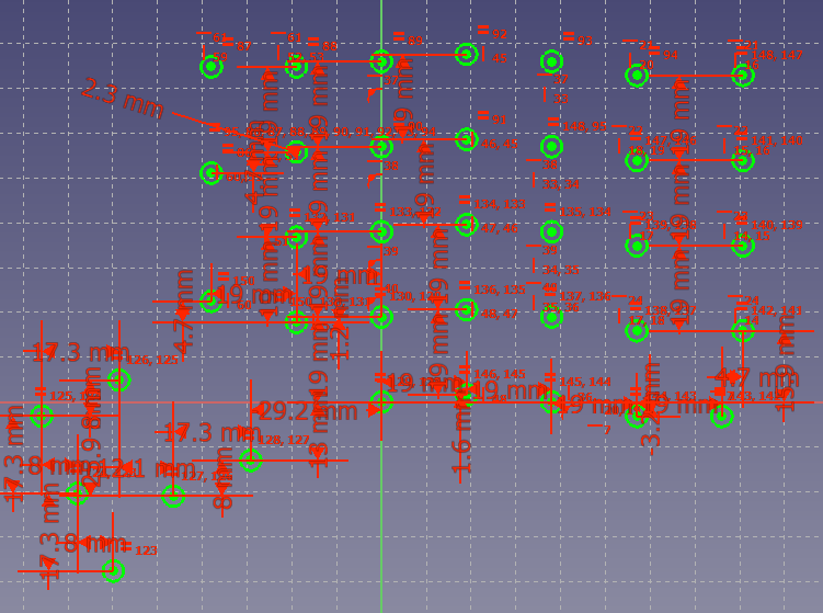
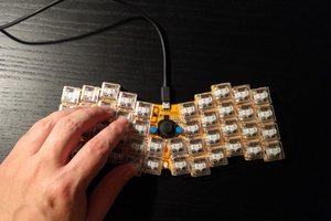
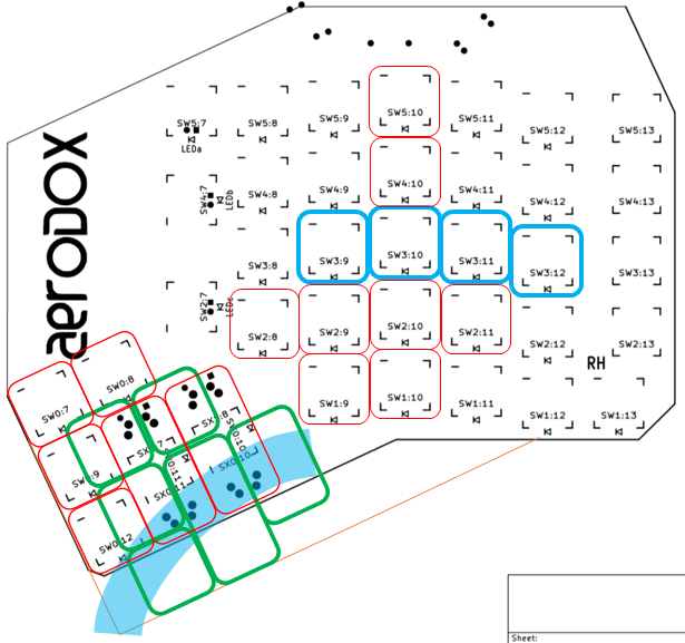
    The red key outlines are the original ErgoDox key locations; they're not all populated in the diagram, obviously. Blue outlines are the home keys (as far as I can tell). The light blue, semi-transparent arc is where I think my thumb naturally sweeps when fingers are on the home keys (referenced to the middle of my distal phalange). The green outline keys are where I'm considering moving my thumb cluster to. The fine orange line is an indicative new board edge.

    Some people have said that the Keyboardio has a better thumb cluster layout, which does seem to map quite well to the  thumb sweep above, but perhaps doesn't provide large enough buttons.

    Do any experienced keyboard users have any sage advice about the folly of an idea to move the thumb cluster like this?

  • Key Switch Footprint

    Simon Merrett05/11/2020 at 01:22 2 comments

    I think I may have managed to make a key switch footprint for the Kailh hot swap PCB inserts/adapters. 

    The reason I want to be able to hot swap my key switches is because I may not want to keep the first ones I try (probably box browns). Here's a footprint which I think is reversible and will save time during layout.

    The only downside I can see at this stage is that the diode symbol could be confusing. Bear in mind that if we're looking down on the PCB, the hot swap insert is connected to the bottom layer (green) and the diode direction we want is in the bottom silkscreen (magenta). I did this because the surface mount diodes are likely to get reflowed on the same side as the hot swap inserts. Obviously, if you are placing a through hole diode, you are less constrained by the reflow, so you may choose to hand solder it on the other side of the PCB, in which case you still need to heed the diode direction on the bottom layer, not the top layer. The rule is "correct diode direction is on the same side as your hot swap insert pads".

    Here's the 3D view of the front 

    And here's the back

    There are only two "user" pins in this footprint - top left rectangle pad and bottom left "D" pad. Note that none of the pads down the bottom are PTH. They are copper annuli and non-plated holes, which adds another layer of complexity for the through-hole-diode constructor but achieves the symmetry required to allow the PCB to work on both sides. It was painful and I needed to use custom pad shapes in the footprint editor, as well as putting the soldermask and paste layer apertures separate to the main pads.

    I thought I was done and then I realised that the mirrored pads that weren't being used would be expecting joins in the ratsnest, so I added more traces and makeshift vias (PTH with same pin number and without soldermask). This one is trying to not get in the way of the LEDs that are in some footprints. 

    Finished footprint (for now)

    I'll see how it goes when I try and lay the board out. Schematic next.

View all 11 project logs

Enjoy this project?

Share

Discussions

Matias N. wrote 05/18/2020 at 21:35 point

Did you use the ergodox PCB design to base yours? Or did you use it for reference? Didn't quite get it from the project logs. Do you know what is ergodox license for the hardware design? On the repo I found it didn't had any.

  Are you sure? yes | no

Simon Merrett wrote 05/18/2020 at 22:15 point

I used it for reference. Did some poking around in their files, mainly to measure dimensions of column offset. Athough I think I got quite far along playing around with their pcbnew and may have posted an image of that, I made sure to go back and generate my own schematic and pcb layout. I'm thinking I need to make the processor separate to the main keyboard PCBs, so that a range of radios and processors can be used with the same key layout. A half-keyboard daughter board.

  Are you sure? yes | no

Simon Merrett wrote 05/18/2020 at 23:27 point

@Matias N. Just found this "Both the keyboard design and hardware files are licensed under the GNU Public License 3" here:  https://www.ergodox.io/#credits

  Are you sure? yes | no

s0 wrote 05/14/2020 at 12:59 point

There are forks of QMK supporting targeting NRF5 hardware. A list of some such boards in the repo of another one is here https://github.com/joric/nrfmicro/wiki/Alternatives. Haven't dug into their BLE support layer but it would be quite doable to crib off the Adafruit libraries for supporting multiple pairing if not currently supported by the forks. They already support the topology of having one hand as both peripheral to computer and central to the other hand as I suggested, which is good, suggests much of the work has been done.

  Are you sure? yes | no

s0 wrote 05/14/2020 at 08:53 point

Cool project. I was considering making an ErgoDox recently with my own modifications to use SMD MCU & USB-C. Is there a reason you went for NRF24L01 rather than a bluetooth module? I like the modified thumb cluster placement. Big fan of the SOICbite.

Did you consider including a USB connection and rectangular lithium rechargeable cells? more components, I know. but at least there are chargers everywhere.

  Are you sure? yes | no

Simon Merrett wrote 05/14/2020 at 09:31 point

Hi @cortices ,thanks for your compliment on #SOICbite Programming/Debug Connector Footprint!

Yesterday, about 12hrs before the Hackaday newsletter dropped into my inbox I found the #Redox keyboard and it's wireless ultron model. My immediate thought was that I had wasted my time embarking on a different design. On reflection, there are two requirements I have that differ from the ultron (wireless Redox).

Firstly, and most trivially, I dislike non-rechargeable and "user removable" coin cells. Even with the stunning battery life that Ultron exhibits, I'm reluctant to build that energy store in. So I'm looking for eg AA or perhaps AAA rechargeable power. A few basic low self discharge batteries should do and are already in circulation in my home. 

The second requirement is that this needs to act like a wireless KVM switch, without the V or the M (yet!). I have messaged @Mattia Dal Ben to ask if he sees any way to do this with the Bluetooth connection. I realise that Bluetooth has basic security baked in and something would need to be added to firmware to use the NRF24L01s but I know how to use them to ensure that only one receiver is addressed at a time. If you have any hints to make the Bluetooth approach work and allow me to switch between multiple computers from the keyboard, please let me know!

Just for clarity, I considered the modified thumb cluster but decided against changing from the "standard" ergodox layout in my first revision, as I don't have any reference to judge my own design against yet. That said, the layout of the #Redox keyboard looks like the best one I've seen so far.

Keep in touch! 

  Are you sure? yes | no

s0 wrote 05/14/2020 at 11:30 point

I had a look at the NRF52840 BLE options around. The BLE support in the Adafruit Arduino-compatible Bluefruit library is simple and easy to use (see https://github.com/adafruit/Adafruit_nRF52_Arduino/blob/master/libraries/Bluefruit52Lib/examples/Peripheral/hid_keyboard/hid_keyboard.ino) and according to this document https://learn.adafruit.com/bluefruit-nrf52-feather-learning-guide/dual-roles-bleuart you can set one to operate as both Central and Peripheral simultaneously. This would allow one of the 'hands' to talk to both the other hand and the computer simultaneously. And it's very simple to have a button that disconnects from the current device and puts the keyboard back in advertising mode. Unfortunately BLE Peripherals cannot initiate a connection, but most OSs will automatically initiate a connection when they find a 'remembered' device. You could then modify the connection code to specifically choose which device to allow re-pairing with (instead of first-come-first-served), to act as keyboard switcher. It might not be as instant as the NRF devices but it handles the encryption for you, and if your computers have bluetooth hardware then there's no need for external dongles. In addition, the NRF52840 could operate as primary microcontroller as well. There are sleep modes for both systemOff (GPIO wake then reboot) and waitForEvent which is a mid-process power-saving mode.

You can use tiny generic NRF52840 castellated modules with a J-Link SWD programmer (or get one with a serial bootloader pre-loaded) to upload the Arduino hex instead of using an Adafruit board.

Having pushed the NRF24L01+s to the very edge on a project a little while ago, I can agree with your affection for them though :) They are super versatile and simple. When I found out they were being discontinued, I bought 10 of the official +PA+LNA modules :)

You know what, now I'm looking at this, it's making me interested in making a keyboard again... I don't do a lot of typing though so I've always just gotten by with an apple one. Maybe I should start working on my own variant with everything above, though it'll have to wait since I have to move house unexpectedly.

EDIT: Doh, I just looked closer and the NRF52840 supports up to 20 simultaneously connected devices, peripheral or central! So if you block off one for the 'non-dominant hand', you could have 19 devices paired & connected concurrently, and choose which one to send the HID output to through some method, maybe associating each with a key while pairing the first time?

  Are you sure? yes | no

Simon Merrett wrote 05/14/2020 at 12:40 point

@s0 You are rapidly winning me over to BLE. Sorry if it seems like I'm using you to type stuff into a search engine but you seem to know more about this and are at least one page further ahead than me! Do you know if QMK will work over a direct BLE connection to the computer? https://beta.docs.qmk.fm/using-qmk/hardware-features/feature_bluetooth suggests this has yet to be implemented with the chip's we're considering.

PS, I'm happy to get going on the HW/construction side and hopefully you will be able to join in once you're settled in the new place.

  Are you sure? yes | no

Similar Projects

Does this project spark your interest?

Become a member to follow this project and never miss any updates