 Simon Merrett
This log is well overdue but I honestly hadn't made any progress until yesterday. All the parts were here but the firmware was putting me off starting the hardware.
Hardware
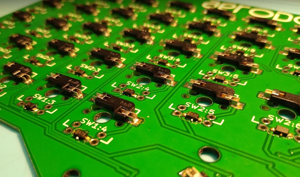
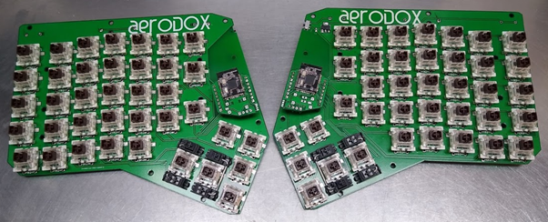
Apart from the opportunity for a pun, I thought I would see how long the diodes and hot-swappable switch holders would take to solder (a) with solder paste dispensed by hand and then the board reflowed and (b) soldering by hand. The solder paste, place and reflow method took me 25 minutes and the hand soldering of exactly the same components on the other half of the keyboard took me 35 minutes. That might not be interesting to you but I have often wondered where the threshold of hand soldering even SMT parts is compared to splodging some solder paste down from a syringe and plopping the parts on top. For clarity, I should say that the 25 minutes didn't include the 10 mins to reflow but I don't count that as I was able to use that time for other things.
Another interesting point about the reflow oven was that the PCB came out slightly warped, which may have been because I went too hot, too long or it may just happen with larger boards and large holes arrayed across them. So hand soldering may hold some advantages in this case.
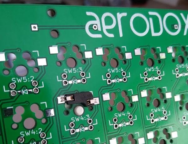
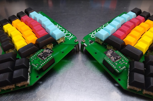
I'm really pleased with the Kailh hot-swap switch mounts. Although this kind of design will suffer from rigidity issues without a (reinforcing?) plate around the body of the key switches, the ability to remove a key switch so I can solder in the vicinity has been great and I will be able to more cheaply move to new switches or a new PCB if I want to.
I'm also really pleased with my double-sided, SMD/through-hole enabled key switch footprints. This dramatically reduced the requirements for laying out traces or parts in kicad. Although I think that a python-based automatic layout script for custom key spacings wouldn't be too hard to do and might make future iterations very fast to generate.
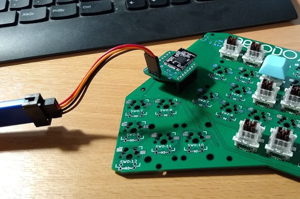
The motherboard idea works well in a "bring up" sense. Although it's not as aesthetically pleasing, perhaps, it was essential for programming and troubleshooting and reprogramming and troubleshooting again (!) that I could easily remove the module from the keyboard. It basically allowed me to prototype on hardware that's good enough for final use.
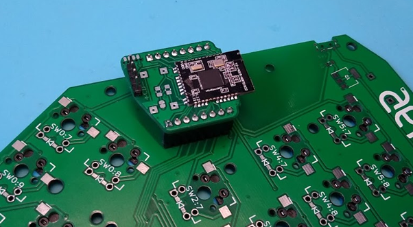
Initially the motherboard wouldn't power up when I switched from the ST-Link power to the batteries. I suspected it was either (a) the 2*AA battery voltage was insufficient or (b) there was an issue with the way I had wired up the reverse voltage protection MOSFET. eBay (in lieu of a datasheet) told me that the voltage wasn't an issue and when I shorted the source and drain pins on the mosfet, the problem didn't disappear... See "Notes to self" below for the culprit.
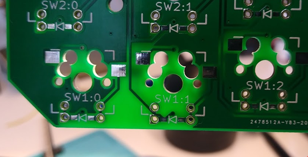
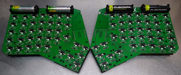
The battery holders have a locating stub moulded into their plastic housing, which needs slicing off for a flush fit - there's no hole in my footprint.
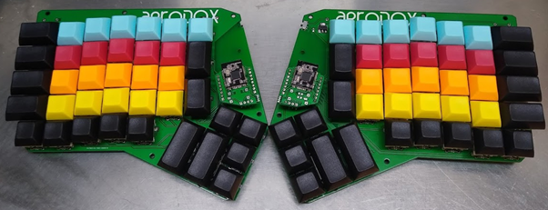
Fortunately, a single M3 standoff is all that seems to be needed for tenting stability for now, until I make a proper frame.
Software
The NRF51 motherboard was set up on Ubuntu with the instructions given at the very helpful #Redox keyboard Github repo. I haven't used this toolchain before so I really appreciate all that @Mattia Dal Ben has done for us there. The original Aerodox idea was to use an MCU and radio module pairing but the NRF51 is a much better arrangement at this stage and this first version of Aerodox is completely based on #Redox keyboard 's wireless version.
I had to spend a lot more time understanding the code for the NRF51s and qmk to have a clue how to get the key presses I want onto the screen. This is partly because I based my matrix on the ergodox and the redox has a rather different layout, which I'll come on to.
The key mapping has begun and I believe I can get all the keys to register now (I had issues with the additional row that Aerodox has over Redox and the column to key mapping). I haven't mapped them all properly because I need to rewrite the key map from Redox to suit Aerodox (with more keys and a different kind of thumb cluster.
There are some significant double types, which might be to do with the debounce in the keyboard side of things. I shall have a play with that. The response of the screen can also be a bit laggy but I could get used to it.
Notes to self
There are several items which I'm just going to list here that I need to address in any publicly released version of the design. If you want more details, say so in the comments:
- Copper pours are not connected between battery protection MOSFET and motherboard ground. A solder bridge fixes this on the current version.
- Battery holder clashes with battery protection MOSFET on the left side - rearrange.
- The Redox column/row matrix wiring goes in the opposite direction to the Ergodox (which I used as my original hardware reference) - this means that the diodes need to be installed the other way round (don't ask me or my hot air gun how we know) and the silkscreen for the diode needs to be swapped direction in the next revision.
Outstanding
I have yet to implement the switching between computers. I want to get the keyboard working nicely with one computer first and will then attempt the KVM (without V or M) switch mode later.
Discussions
Become a Hackaday.io Member
Create an account to leave a comment. Already have an account? Log In.