The KORE controller have LEDs for all potmeters, buttons and the rotary encoder. In previous log I showed how to connect the transistor controlling the LEDs for the rotary encoder to keep them constantly on. These are the only LEDs controlled as a group by a transistor. All other LEDs have individual control lines.
The ATmega2560 has enough IO driving strength to directly control the LEDs. It can sink currents up to 10-20mA pr pin and 100-200mA pr port (varies from port to port and VCC voltage). So LEDs can either be wired to be constantly on or controlled directly by IO pins on the ATmega2560 as you see fit. I decided to only control the LEDs for the 8 buttons by the potentiometers, and the 4 playback control buttons (Stop, Play, Record and Speaker symbol) from the ATmega2560. All the other LEDs I wired to be constantly on.
The board was originally designed for 3.3V operation, so the existing series resistors for the LEDs would be a bit too weak for 5V. They can just be left in place, and I added instead new 2K2 ohm series resistors to ground to power the LEDs from 5V. This gives a good brightness at a moderate ~3mA pr LED.
The LEDs are active low, so for the ones that should be wired to constant on, connect the 2K2 ohm resistor to the LED, and the other end of the resistor to GND. To find out which terminal of the LED to connect to, you can make a probe with a cable connected to ground attached to a 2K2 ohm resistor, and use the other pin of the resistor to check which LED pin makes the LED light up.
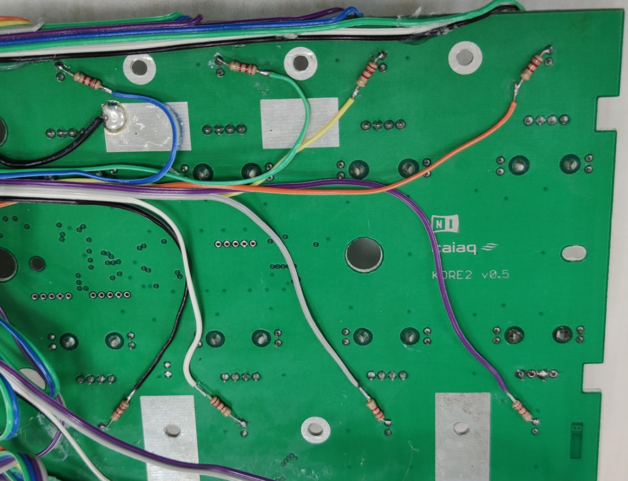
This picture show the wiring for the 8 LEDs for the buttons by the potentiometers. The resistors should be connected to the top pin of the LEDs
 Wiring for the playback control button LEDs to be connected to the Arduino (the 4 resistors at the bottom), and the LEDS for the control and navigation buttons connected via the resistors directly to GND to stay constant on. The black insulation tape is the area where the mega2560 Arduino will be placed.
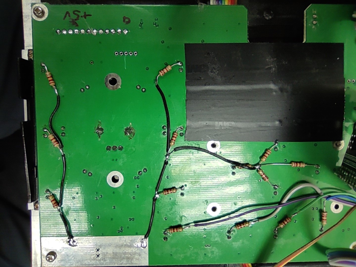
Next step: get it all connected to the Arduino board.
Discussions
Become a Hackaday.io Member
Create an account to leave a comment. Already have an account? Log In.