 Jason
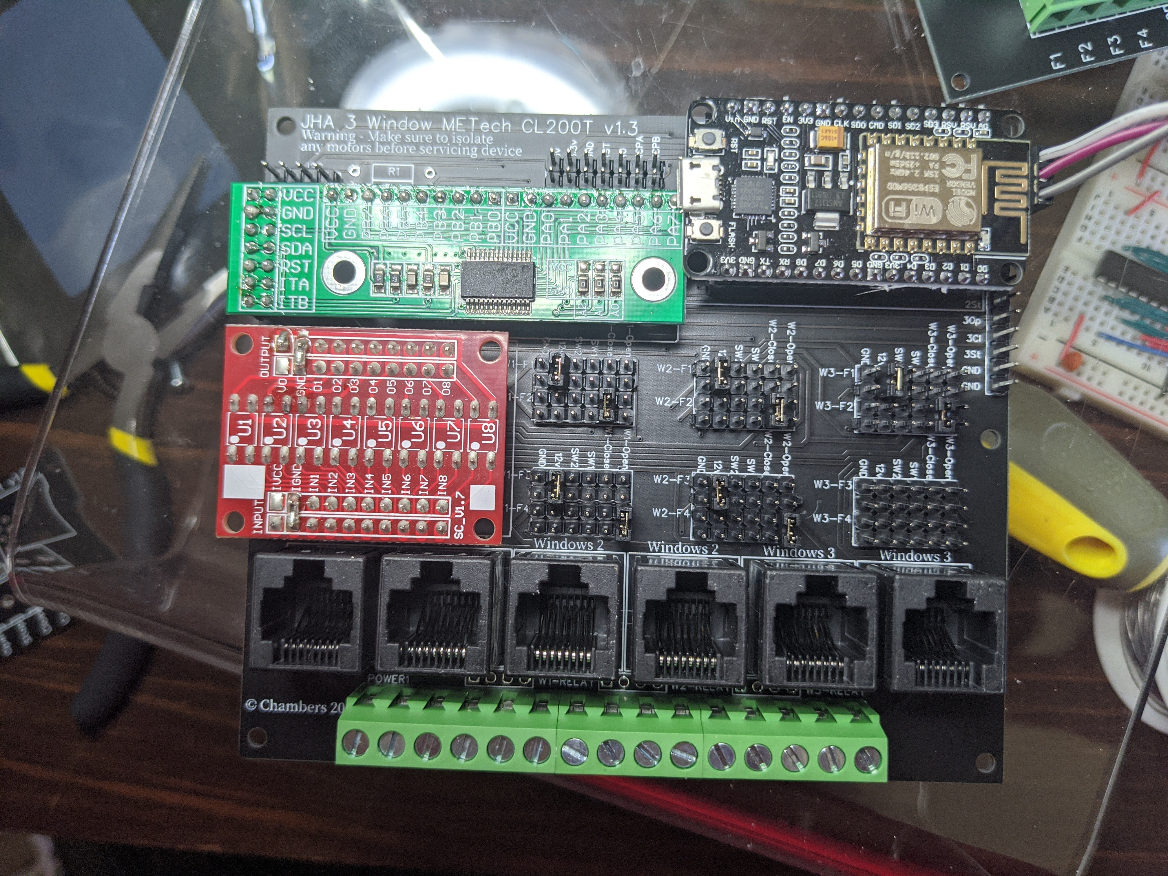
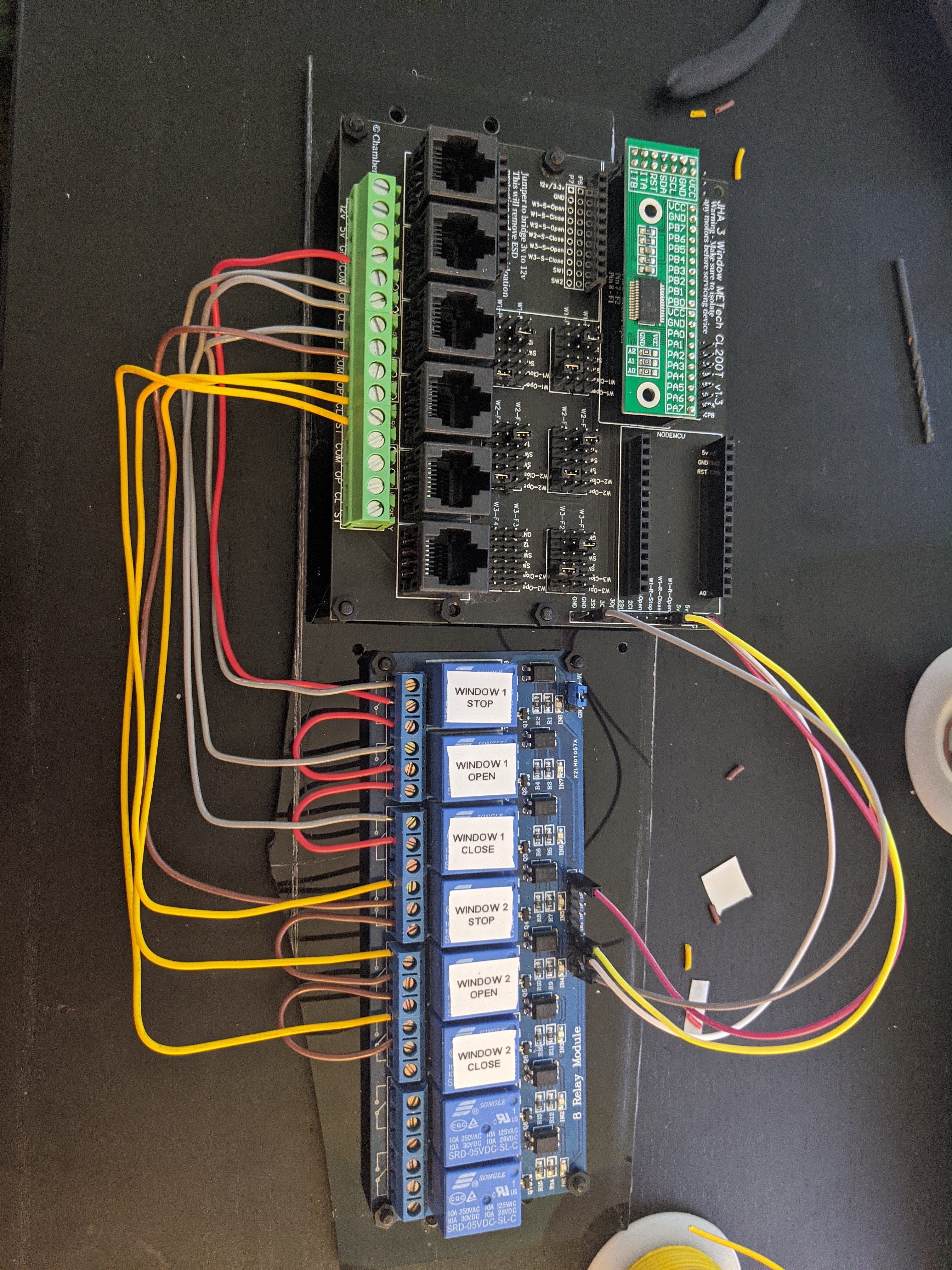
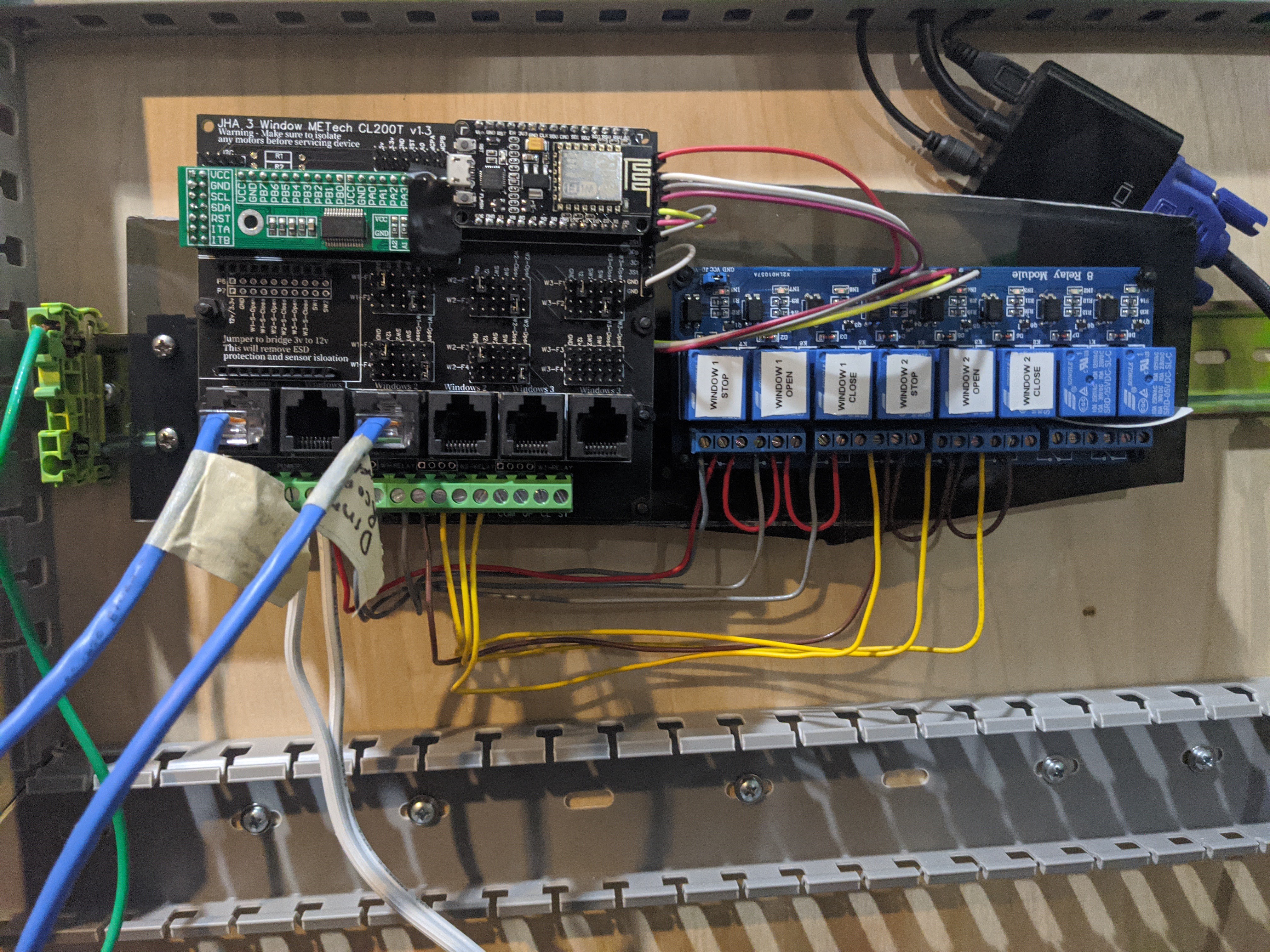
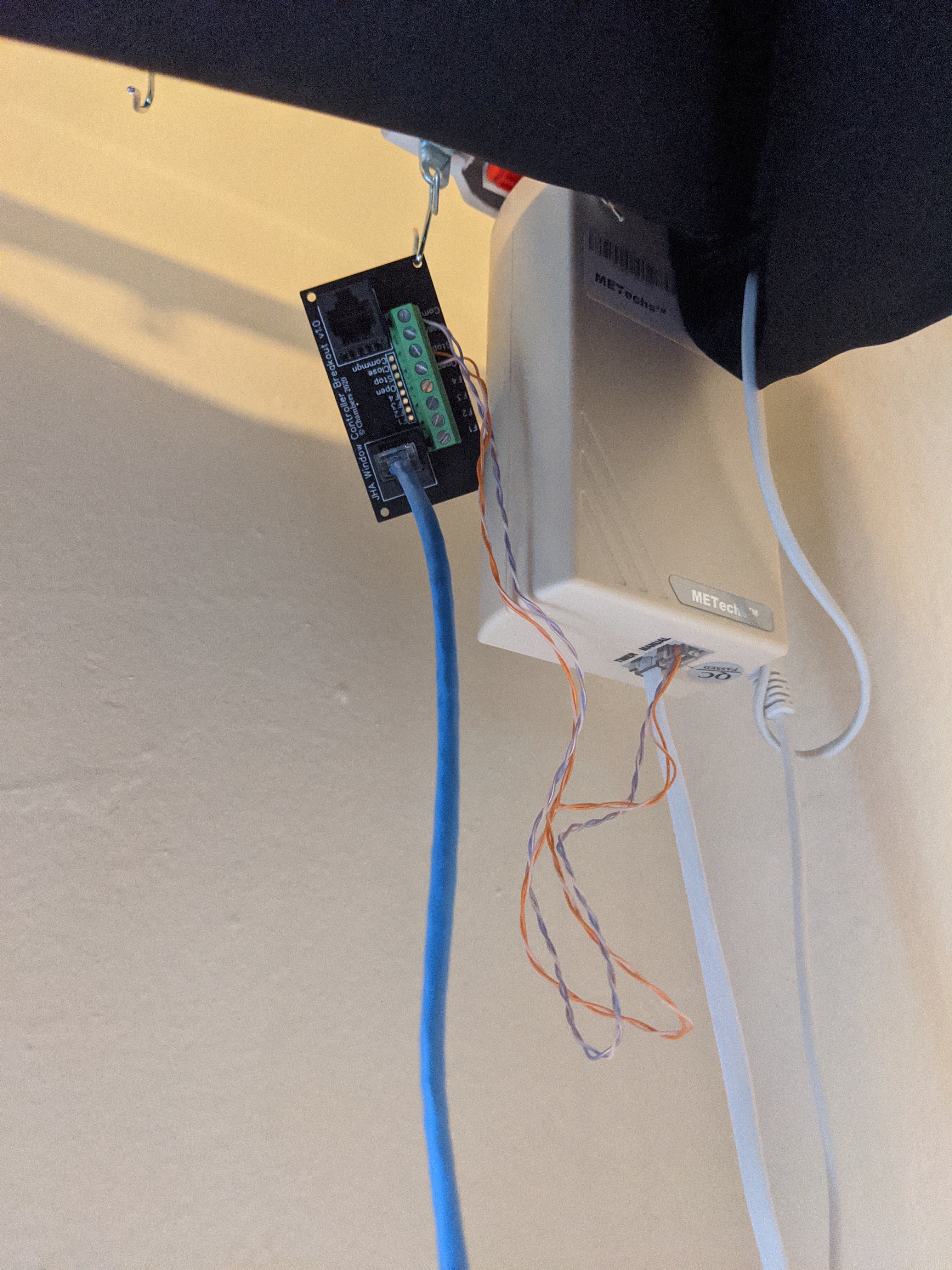
JasonThe PCBs have come in and assembled. I created 2 boards, one that will be the central controller and a second optional breakout board. The breakout board is only needed if you won't don't want to "directly" wire the controller to the motor housing.
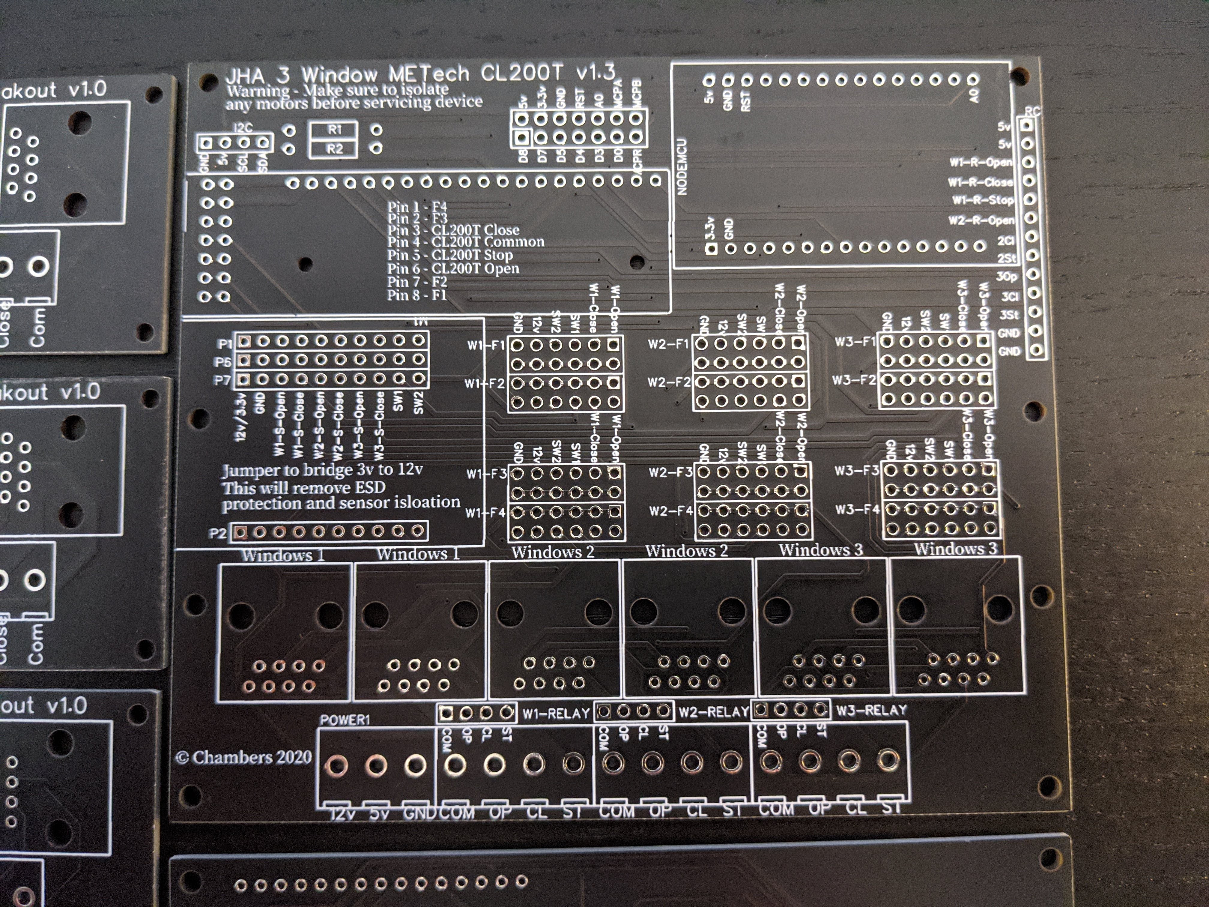
The controller board can route 4 functions to each zone. There are 2 global inputs and 2 "zone" inputs. A total of 3 switches and one common could be routed to any zone over a CAT5 cable. If a separate common line (12v) is routed separately, such as with my LEDs, you could return 4 switches.

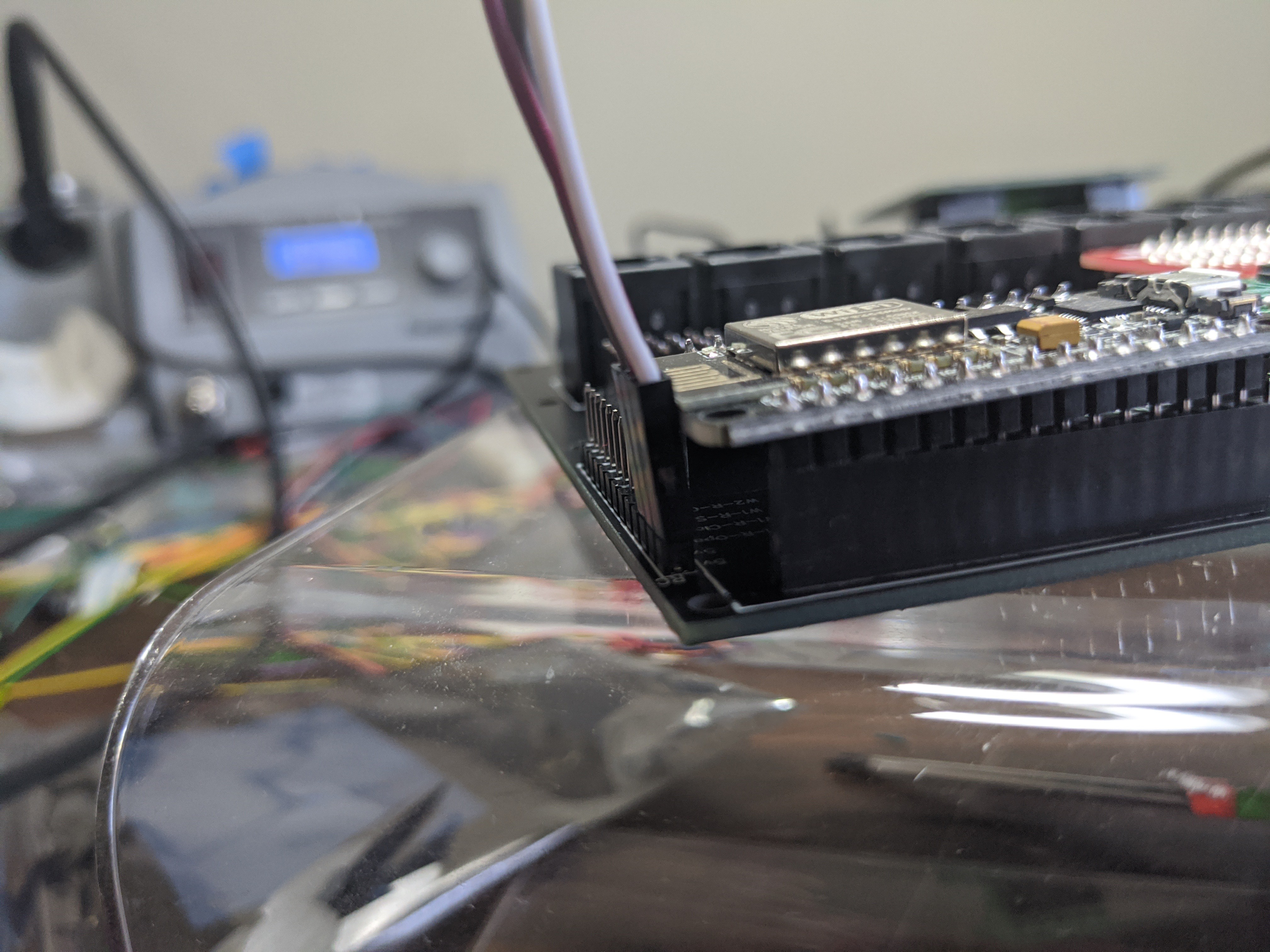
I was a bit tight on a few of the interconnects and the relay header butt a bit too close to the NodeMCU and has to be slightly bent.
But overall the board turnout great!

Discussions
Become a Hackaday.io Member
Create an account to leave a comment. Already have an account? Log In.