 Anthrobotics
Here is the current wiring setup for flashing a generic ESC with new firmware. The layout of soldered wires for re-flashing will depend on the model of ESC.
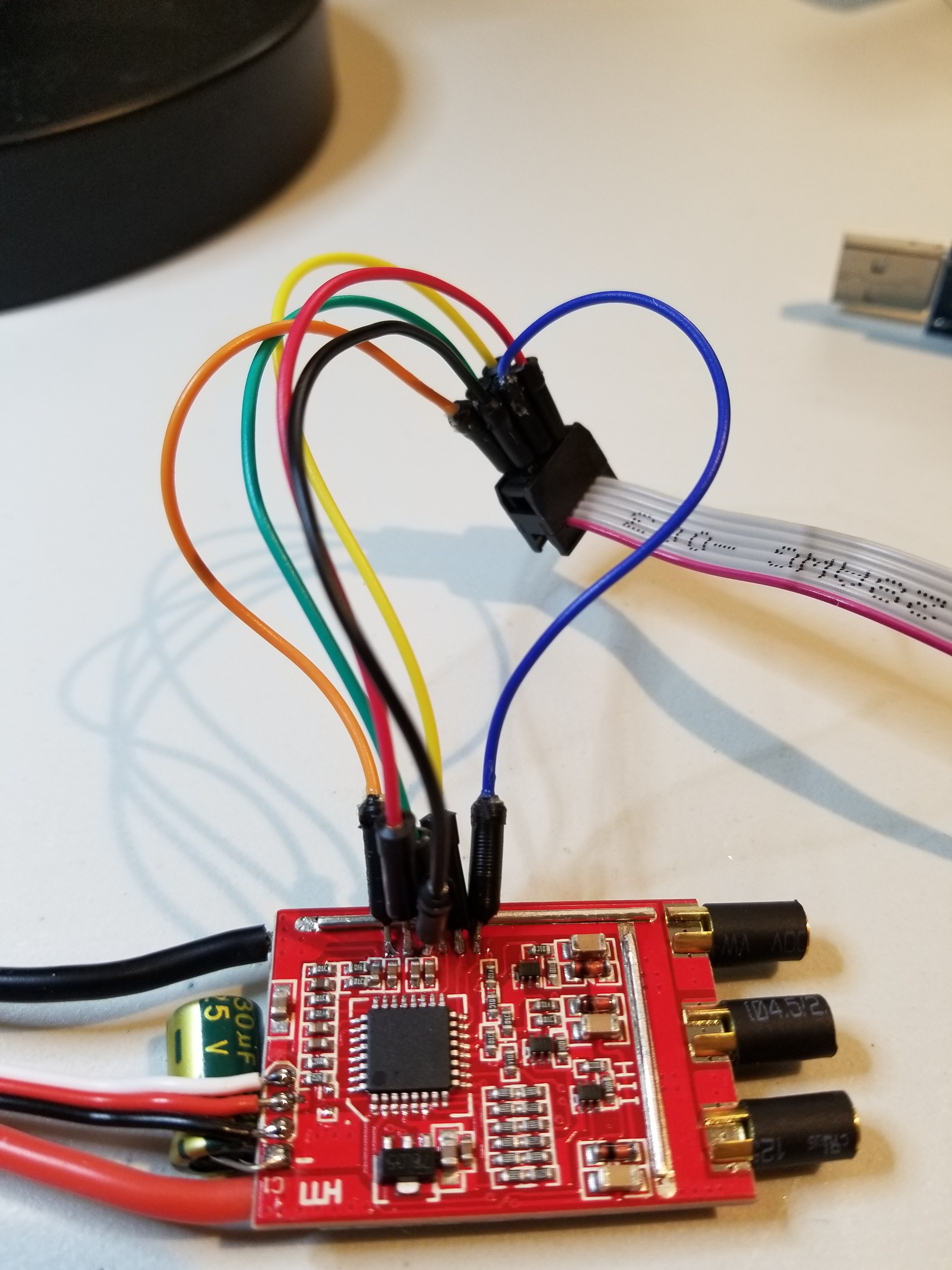
Six wires are soldered onto the six exposed pads on the PCB. They are, from left to right,
RESET > VCC > GND > SCK > MISO > MOSI
The wires are connected to a USBASP programmer using a 6 to 10 pin ISCP ribbon cable, following the standard Arduino ISCP pinout.
USBASP Programmer
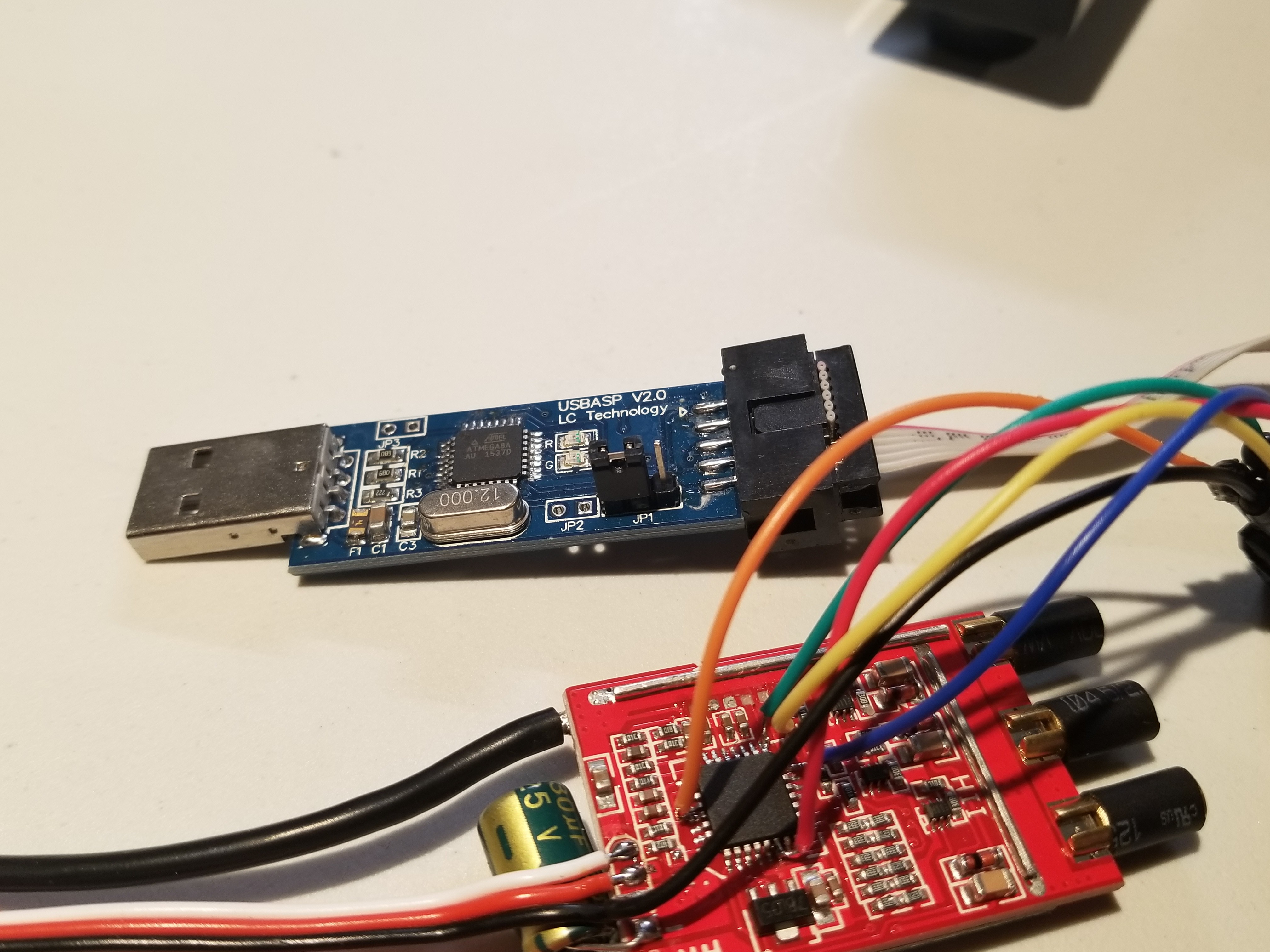
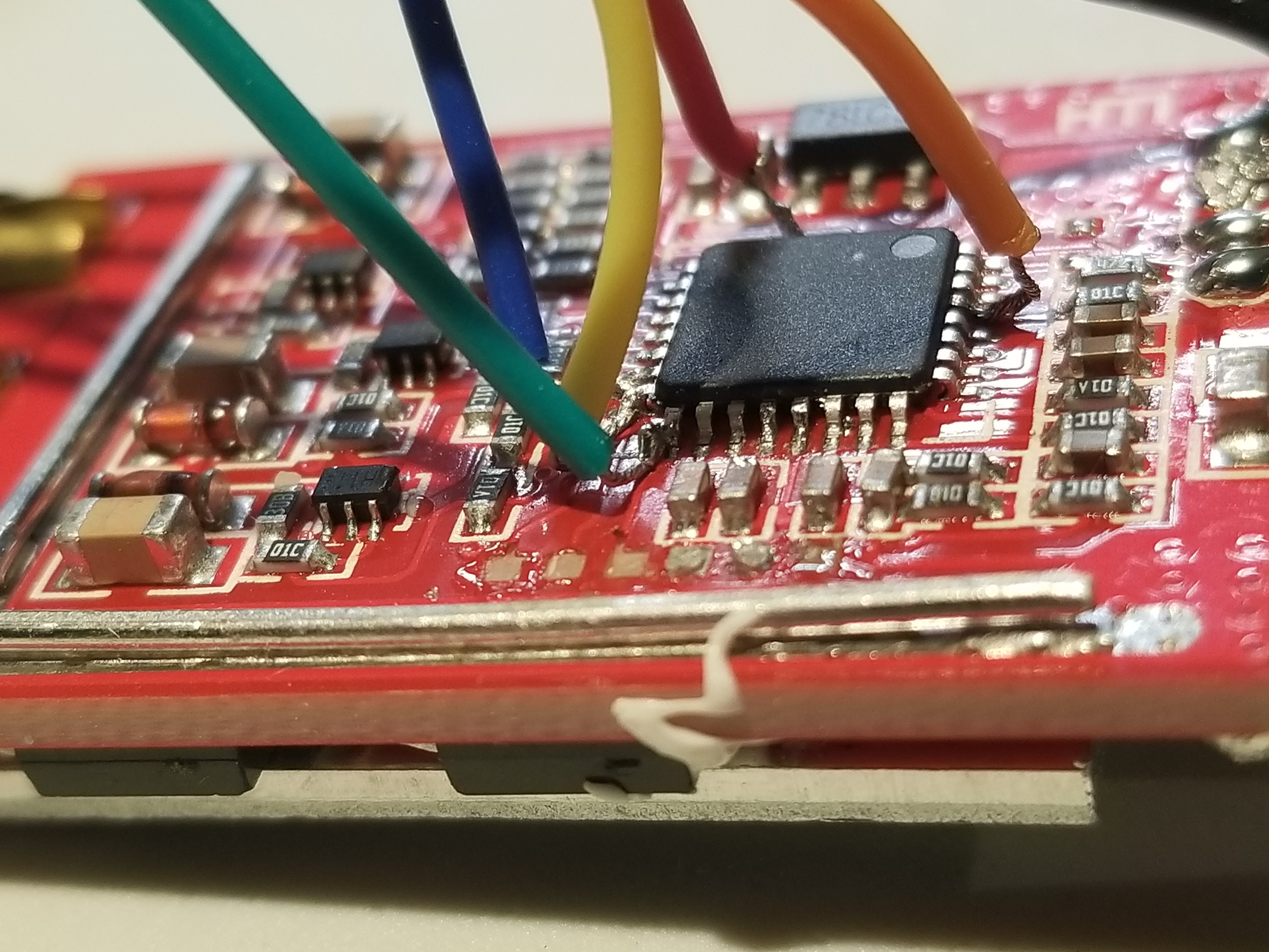
It can be hard to tell from the image as the plastic bits on the jumper wires are crammed together. We actually ended up just soldering to the ATmega8 chip directly as the pads ripped right off the PCB!
Fixing the botched attempt. Notice the carnage on the second image...

With that out of the way, hopefully we can flash some different firmware to the chip. Fingers crossed, we won't have to go looking for another alternative. If we do, hopefully it is also affordable to fit the bill for our project.
Discussions
Become a Hackaday.io Member
Create an account to leave a comment. Already have an account? Log In.