 Thomas
I'm pleased to report that the project is complete and the modification is working well. Here's a rundown on the final stages of the process:
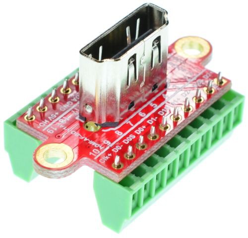
1) The female HDMI breakout I had originally ordered worked well for testing, but I soon learned that it was not easy to mount to the iMac case. So I ordered a different breakout from the same ebay guy (see the list of project components for a link), but this time I was smart enough to pay the extra $2 for him to solder the HDMI pins to the breakout board. This soldering requires a very fine soldering tip and strong magnification. The first time I tried this I used my daughter's microscope, but even that didn't keep me from somehow shorting two of the leads and ruining the adapter—so the $2 is worth it. The pins to the screw terminals are large enough that you can solder those yourself without too much difficulty.
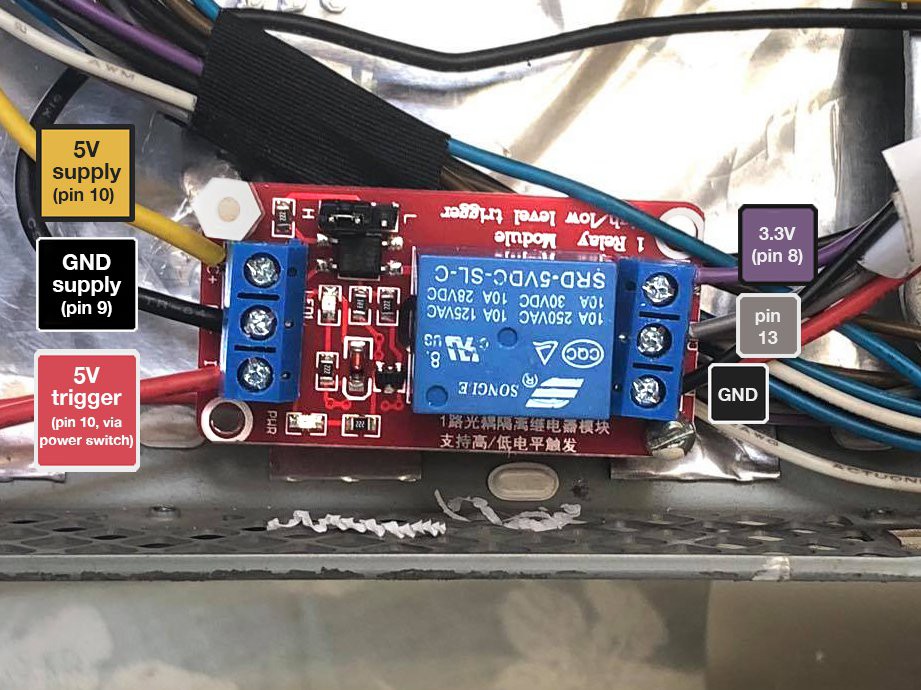
2) As mentioned in previous logs, power to the monitor is controlled by shorting two of the leads from the large female connector that normally plugs into the logic board. Shorting pin 13 to ground turns on the inverter, and shorting pin 13 to 3.3V turns off the inverter. This means that a standard on/off switch for power won't give us the control we need. So instead I used a 5V relay circuit, powering it with 5V from pin 10 and ground from pin 9, and routing a branch of that same 5V line through the user's main power switch to toggle the relay on/off. On the other side of the relay circuit there were also three wires: the common wire was pin 13, which the relay connected to either GND, or pin 3.3V (from pin 8). I used a relay where the trigger could be set either HIGH (in my case 5V) or LOW (ground)—either will work for this circuit. I mounted the relay to one of the plastic posts that was originally used to affix the logic board to the computer, and then used an M3 spacer to add support on the opposite corner.


3) Once you've wired the monitor cable into the female HDMI breakout, be sure to go through and make sure none of the data connections are shorted. All of the "shield" wires from the data lines are ultimately connected, so you should have continuity between HDMI pins 2, 5, 8, and 11. I somehow also had continuity between HDMI pins 10 and 11, where there should be no continuity. On very close inspection (using a high-powered magnifying glass) I saw that I had somehow nicked the insulation on the data line that went into pin 10. Because the shield lines are uninsulated, this caused a short. Difficult to diagnose, but easily fixed. I should also note that my research indicated that shortening any of the monitor cables could be problematic, as their resistances are carefully balanced to prevent distortions in the image. I don't know how much of this is relevant, but I tried to leave the cables intact and the resulting image is crystal clear.
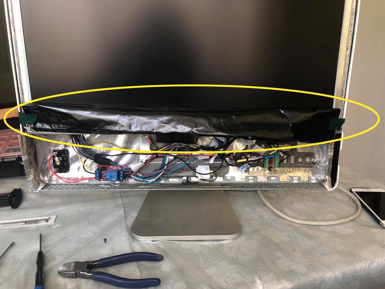
4) It is necessary to cut off and remove the thin plastic shroud that covers the area below the screen. It is metallic on the inside and if it comes into contact with live areas of your circuit could cause a short. This happened to me while demonstrating my work to my friend who commissioned the project, which was a bit embarrassing. So cut that thing off!
5) Pin 7 (LCD_PWM) and pin 1 (3.3V) should be soldered together and insulated with heat shrink tubing. I've read of others using a 1K resistor when shorting these pins, but I elected not to do that and haven't had any problems.
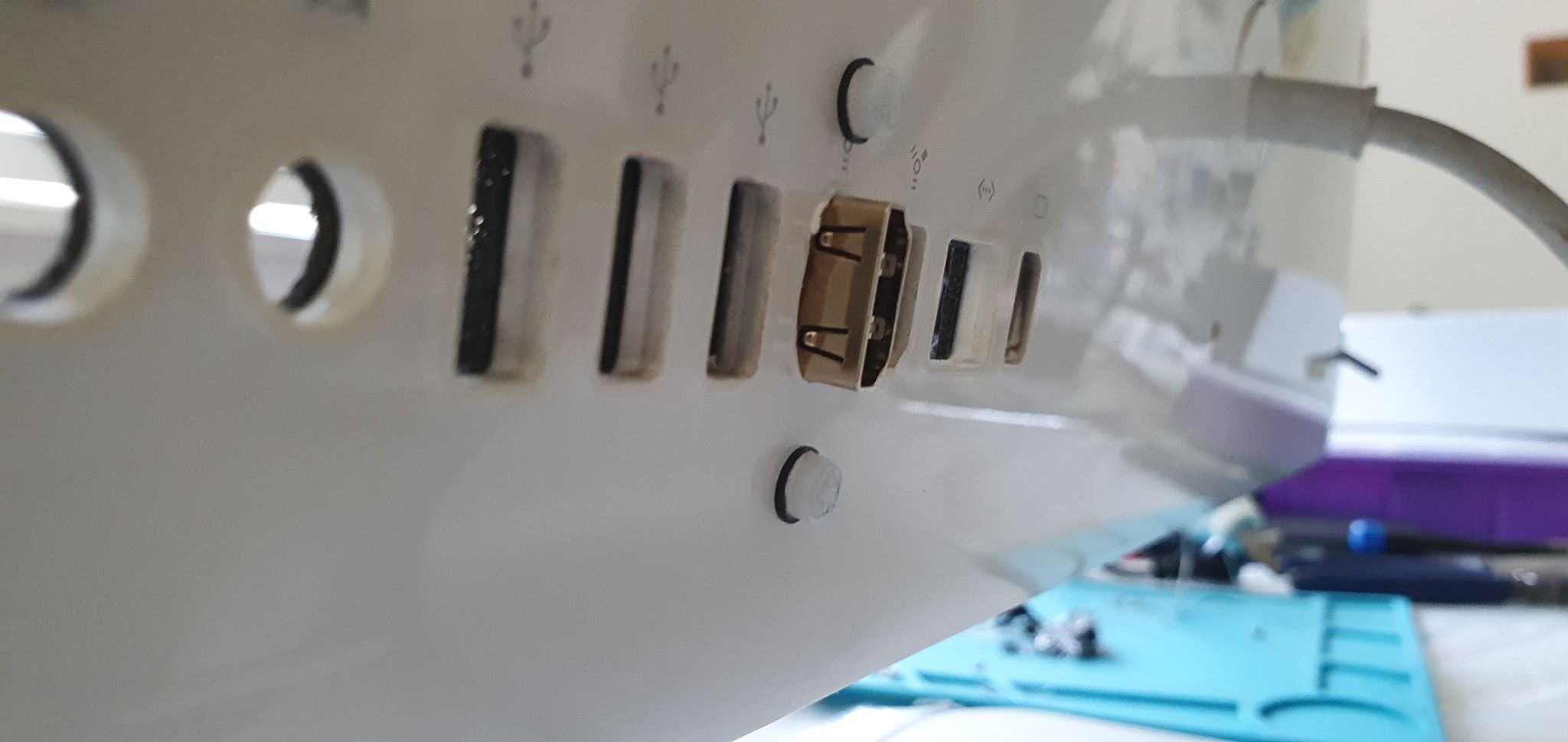
6) I mounted the female HDMI connector through one of the existing USB ports on the back of the iMac. Be sure you add some sort of insulating material over the pins on the connector's screw terminal block on the underside. If they managed to poke through the thin material apple has around the USB port they will come into contact with a metal layer, and this will cause a short.

7) I was initially a bit concerned about heat, so I thought I would reinstall one of the three fans that came in the unit. But these fans are not controlled by voltage alone, and without the logic board I couldn't figure out how to activate them. Once everything was up and running and I had reattached the iMac cover, I let the unit run for a few hours to test heat. The area near the inverter board was warm to the touch, which I think it normal, but it never got hot. The venting on the back of the iMac seems to be enough to keep things cool.
8) I had a few old vintage switches sitting around that were almost exactly the same size as the hole where the iMac power button is mounted. With some careful filing and some love from the glue gun, we have a main power switch with a solid, mechanical action that gives the project a bit of personality.
That's it! I'm happy to answer questions via DM if anyone is attempting this mod and needs clarification.
Discussions
Become a Hackaday.io Member
Create an account to leave a comment. Already have an account? Log In.