 sx107
sx107I'll split this desctiption into several steps later
Introduction
You may want to check out the vid I made about this synth first (it's in Russian, but English subs are available):
Here I'd like to share everything I learned about this synth up to this point to maybe have your interest in this vintage synth and show how it can be repaired and modded. This article, in particular, it's "synth schematics" may be interesting not only for someone who actually owns this synth, but also for people who are generally interested in how analog synths work.
I didn't make any complex mods like adding MIDI or CV control, but I am planning on doing that in the future.
First of all: description of the synth. Lell UDS is a soviet drum synth produced at least in the 80s (if not earlier), the one I bought was made in 1989. It has two independent channels, each with a tone and noise generators (the tone part produces a triangle wave). Each sound generator has its own attack-release envelope volume control, the tone generator also can change its pitch according to the same envelope as the volume one. Noise generator has two timbre controls - "спектр" (spectrum) and "тембр" (timbre). Both generators are then mixed in each channel with a "баланс" (balance) knob, and, finally, both channels are mixed using volume ("уровень") controls. The "snap" ("щелчок") is a separate generator making the sound more, well, snappy.
The synth was originally intended to be connected to two drum pads, therefore the input circuit has a gain/sensitivity ("чувств." for "чувствительность", sensitivity) knob for each channel.
Is it the most amazing sounding synth ever? Nope. Is it an interesting sounding synth? Not definitely. Can it be modded to sound somewhat decent? Hell yeah. Is it worth it? For me - yeah.
Disassembly
For the most part I've shown the whole disassembly process, however, I'll clarify some points just in case if someone will stumble across this article while attempting to mod this synth:
1. A couple of screws is hiding behind the front panel "onlay". The onlay can be taken off by carefully prying it off with something like a knife.
2. Nope, the power cord can't be taken off without cutting it and you will probably end up with the back panel hanging on it.
3. Just to be sure: before you even start the disassembly, turn off the synth, pull the plug off the power outlet and then turn on the synth for a while to discharge all the caps. There are no high voltages on the main boards, but it is still a mains voltage instrument. Be careful.
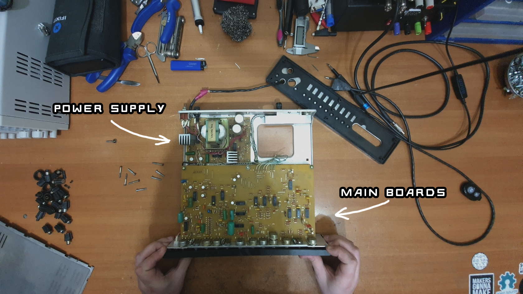
Inside three boards are welcoming us:
- a bipolar +/- 9V transformer power supply, which also produces some kind of reference voltage, which I, unfortunately, forgot to measure. The reference voltage is not present in some versions of this synth if I understood the old schematics correctly. The reference voltage is used in the input amplifier circuit.
- Two almost identical main boards (soundboards, if you will c: ), one for each channel, one beneath another.
The power supply, unfortunately, is a pain to remove, but with some soldering kamasutra you will be able to replace the electrolytic capacitors which most probably will be open-circuited with no visible leakage. On other hand, the main boards are much easier to remove, just unscrew all potentiometers and three screws insides that are holding it and you are in.
What will prevent you from taking the boards out of the case, however, is a mess of cables interconnecting everything and, yes, you've seen right - directly soldered to each board. I haven't repaired a lot of old synth, but If I understand correctly, this practice was quite widespread on the west a decade before this synth hit the market. Fortunately, the spacing between cable mounting holes on each board is exactly 5 mm, so you can easily install some connectors with 5 mm spacing. I have used terminal blocks. Installing connectors will make the reassembly job much easier.
Synth schematics
Overall description
Most soviet synth schematics can be found on the http://www.ruskeys.net. I've grabbed mine from this website as well. There are two Lell UDS schematics on this website - possibly, for two different versions of this synth, but they don't differ that much.
I won't go much into the power supply schematics on the right of the pic. It is relatively straightforward, just a transformer with two output coils, a rectifier and two linear regulators made using discrete components (I don't understand why, though. LM317 clones (КРЕНs) should have been already available in Soviet Union by that point)

The main board schematics are much more interesting. I've split them into several blocks (1-9) for the ease of explanation.
The signal from the drum pads first comes into the preamplifier (1), which also removes the DC component of the signal and passes through only its positive part. Through a VT4 emitter follower the signal then comes into three blocks simultaneously: an envelope generator and a voltage-controlled amplifier (VCA herein) for the noise generator, envelope generator and VCA for the tone part of the sound (3) and a "snap" ("щелчок") generator in blocks 5 and 4. VCAs are essetially "volume potentiometers", which change their value according to the control voltage fed in. The input sound for the VCAs is generated in blocks 6 (tone generator) and 7 (noise generator). The VCA outputs are then mixed together on the R84 balance knob, the snap signal is also mixed here through the R97-R98 resistors. The mixed signal is then coming to the output amplifier/mixer (9) through the R101 volume potentiometer. This amplifier (9) mixes the signals from two channels (the second board is connected to the first one) and is installed only on one of the main boards. And, finally, we have a sound output.
Snap
Let's look at the snap generator first. The snap signal consists of two separate sounds - a noise part in the block (5) and a "tone" part in the block (4).
The block (4) is essentially a lowpass filter with a cranked resonance set by the tuning potentiometer R84. This lowpass filter is put right after a C17/R77 highpass filter. If I understand correctly, this block outputs a decaying sine signal. In this hackaday article something similar is built using Twin-T filters, the same principle is used in the Bastl tea kick module, for example. Since the block (4) is essentially a high-resonance bandpass filter, the input signal is not required to be a perfect impulse, it can be literally any sound and the output will somehow still represent the sound characteristics, so you can experiment a bit by feeding different sounds into the Lell UDS synth.
The noise part of the snap sound is generated in a yet another envelope generator and VCA (5), which changes the volume of the noise generated in block (7). The input impulse passes through the VT3/R7 emitter follower, which, in turn, charges the C9 capacitor through the VD2 diode. When the impulse ends, the C9 capacitor discharges through the R11 resistor (VD2 prevents it from discharging through VT3 and R7). A simple envelope with a release time set by R11 and a zero attack time (almost zero, actually, since the input impulse can have some rise time) is therefore generated. The voltage range of this envelope will be from -9V in minimum up to 7.5V max. This voltage is then dropped trough diodes VD5-VD8 connected in series and R17, R25, R26 voltage divider. Finally, the envelope comes to the VCA built around the D3 IC. This IC (КР159НТ1Д) is a pair of matched transistors and the overall VCA schematic on three transistors built here is quite widespread in synth schematics. You can see it implemented and read a bit about it here (Projects ⇾ Yusynth 000 → Simple VCA), here and here (I'd recommend the last link the most). In my case, thought, the matched transistor pair IC was replaced with a ready-build differential cascade IC - КР118УД1Б, but it doesn't change anything significantly. The output differential amplifier of the VCA is built on the D5 operational amplifier (opamp herein). The output of the block (5) is essentially a really short burst of noise.
I should note that both blocks 4 and 5 are in a way velocity-sensitive: the louder the input signal, the louder the output.
Finally, the outputs of blocks (4) and (5) are mixed through resistors R56 and R92.
Blocks 2 and 3
Blocks 2 and 3 are envelope generators for the noise and tone signals respectively. Their schematics are very similar to the one we've seen in block (5) and work essentially in a same way with only a few exceptions.
In block 2 right after C10 (which serves the same purpose as C9 in block 5) a R32/C14 RC-filter is installed, which forms the envelope attack. R23 potentiometer changes the envelope decay (release) and R32 changes the attack (rise) time.
In block 3 R46 changes the release time and R29 changes the attack, but it should be noted that only the signal before the attack-forming RC-filter is fed into the VCA control voltage. The RC filter (which is actually in block 6) changes the attack of the frequency envelope, not the volume envelope and, therefore, the volume envelope for the tone generator always has a minimal attack, unlike the noise volume envelope. Let's jump intro block 6 now.
Block 6: tone generator (VCO)
The block 6 is essentially a voltage-controlled oscillator (VCO). A VCO is an oscillator which changes its frequency according to a certain control voltage, the higher the voltage, the higher the frequency. Building one is relatively easy, just make that voltage control a current that charges some capacitor and discharge the capacitor as soon as it reaches a certain threshold voltage and you have a VCO with a saw output. Building a good one is quite hard, though, because most of them are build with a precision logarithmic response in mind (like 1V per octave). Not in our case, fortunately: the VCO in Lell UDS synth is very unprecise, but since it is a drum synth, high precision is not required.
As I already said, on the input of this block R29/C13 RC-filter is installed which forms the attack for the frequency envelope. The decay part of this envelope is formed in block 3, therefore, the decay/release of this envelope is the same as of the volume envelope. The envelope voltage is then dropped on VT12 and a bunch of diodes (the voltage drop is somewhere near the 9*0.6V on diodes + 0.6V on transistor, therefore 6V of voltage difference overall) and R41/R42 voltage divider. The unmarked "спейс" ("space", yeah, don't ask) potentiometer attenuates the envelope. This envelope is mixed with a voltage produced by the R59 resistor and R55 potentiometer ("тон", "tone" or "frequency") which sets the constant voltage, by which the envelope is offset. If the "space" potentiometer is set to zero, the control voltage for the VCA won't change at all and will be set only by the R55 pot.
The final envelope then comes to the VT16 transistor base, which forms two antiphase signals on it's emitter and collector. The collector voltage will be -9V + R62 * Ic, the emitter voltage is -9V + R63*Ie, where Ic is the collector current and Ie is the emitter current. Since the transistor base current is relativelly small, Ic is approximately equal to Ie. The R62 tune pot sets the symmetry of these signals and, if I understand this circuit correctly, should be set so that the amplitude of both signals is the same (somewhere around R63 value, while taking the base current into accout).
The collector current changes from 9V to 0V, the emitter current changes from -9V to 0V. these two voltages then open the VT14 and VT18 transistors, controlling the amount of current passing through them. These transistors control the rise and fall time of the triangle wave (they charge/discharge the main VCO C21 capacitor), their influence is limited by the VD30/VD31 diodes. Since the amplitudes of the two signals comming from the VT16 schematic are the same, the current through these transistors should be the same as well and, therefore, the rise and fall time of the triangle wave are the same (duh). The higher the voltage of the signals from the VT16, the more current passes through VT14/VT18 and the faster C21 is charged/discharged, and, therefore, the higher the frequency.
The D6 opamp is a comparator with hysteresis (a Schmitt trigger, if you will). The threshold voltages (hysteresis) are set R88 and R85. Let me explain how it works, if it is obvious for you, just skip the explanation.
Say, the comparator currently outputs a positive voltage, the positive power supply voltage, therefore, 9V. The C21 capacitor is gradually charged through VT14, VD31 and R76. VD30 doesn't let the capacitor to discharge through VD30: the voltage on it's cathode is lower than on it's anode and, therefore, it does not pass any current and this situation will stay during the whole charging process, since the voltage on it's cathode is almost the maximum voltage achievable in this curcuit.
As soon as the voltage on C21 will reach the voltage on the positive input of D6, equal to 9V (comparator output) * R85/(R88+R85) (voltage divider formula), the comparator will switch its output to -9V, the threshold voltage will change to -9V*R85/(R88+R85), and a discharge process will begin through VD30, VT18 and R70. Again, as soon as the C21 voltage drops below the threshold voltage, the charging process begins and the process loops indefinetely.
The VCO output is produced by the C21 capacitor voltage, which passes through yet another VT19/R96 emitter follower, C25 DC blocker capacitor and a bunch of resistor into VCA in the block 3. Don't let the R99 resistor confuse you, it is just a part of the VT20/R99 emitter follower.
Therefore, we are finished with the tone part of the signal. Potentially, three mods can be made here:
- By injecting a current into the VT16 transistor the frequency can be changed, therefore it is possible to add an external frequency CV control. Of course, as I already said, this VCO is not precise at all: it will drift with temperature significantly and the control is not logarithmic at all. So, no perfect standard 1V/octave control, but what did you expect?
- The VT19 base can be connected to the non-inverting input of D6 (pin 5), which will make the output signal not a triangle, but a pulse. With the same amplitude. So, just cut a wire and install a switch selecting whether the VT19 will be connected to C21 or D6 pin 5.
- By playing around with the R70/R76, the rise/fall time symmetry of the output triangle wave can be broken. Even up to a point, where discharge or charge processes will be almost instant, so that the output signal will become a saw wave. And, if the switch in mod 2 is set to the pulse position, then the pulse width can be changed with the same R70/R76 assymmetry! I'd just install like a 2k dual-pot instead of these two resistors.
Therefore, with some easy mods, you can add CV control and make the output a triangle, saw or a pulse with changeable pulse width (that's not PWM: the pulse width is not modulated by any voltage per se). I am sure that a lot of other mods can be made in case of this VCO, it is very easy to play around with. I didn't make any of there mods yet though.
Noise generator (block 7)
In this block we see the only digital ICs seen in this synth: D2 (кр176ир10, that's a CD4006 shift register soviet clone) and a bunch of good old К561ЛА7 NANDs (CD4011). The schematic built around the D4 scheme is essentially a XOR gate built using NAND elements. If you don't understand digital logic ICs, I'd recommend you check out the nandgame.com website, where you will build an entire computer from simple NANDs.
The schematic around D1 IC is an astable multivibrator producing a clocking pulse signal for the D2 shift register. The first timbre knob, R8 "спектр", changes the multivibrator frequency. The last two outputs of the D2 shift register are connected to inputs of the XOR gate built around D4, and the output of this XOR gate is connected to the input of D2. Therefore, this whole schematic is a simple "xorshift" noise generator. It is quite widespread, I won't include any links, it can be googled easily.
The output of this noise generator is directly into the VCA inside block (5), forming the noise part of the "snap" signal. The same signal is also fed into a bandpass filter build around D10, the central frequency of which is set by the "тембр" ("timbre") dual potentiometer. After it, the signal is passed into the block 2, which, as I stated before, contains the envelope generator and VCA for the noise generator, thus the whole noise tract is complete.
I don't know which mods can be made here, no ideas. Maybe the noise generator can be replaced by a regular transistor noise or fm-based one, but why though? Any CV control is also quite hard to implement here, since all of the parameters are set by potentiometers and nod control voltages/currents, so you will have to use voltage-controlled resistors for that, like optocouplers or something based around the LM13700 IC.
Output circuit
The output circuit is very simple. Snap sounds from blocks 4 and 5 are mixed through resistors R56 and R92, forming the final snap sound, it's volume is set by the R97 "щелчок" potentiometer and through R98 is mixed with the "balance" ("баланс") knob output. The "balance" knob mixes two signals from blocks 2 and 3 through R90 and R86 respectively. The final signal is fed into VT20/R99 envelope follower and R101 volume potentiometer, and after that the two channels begin to differ: block 9 is installed only on one of the boards. Block 9 is essentially an inverting mixer, through R100 and R112 signals from both channels come into it, and the gain is set by R109. The opamp output is fed through a protection resistor R110 and a high-pass DC-blocking filter C34/R111. Phew, we are finished here.
Repairing
If you have any non-standard problems, consult the schematics, I hope that my explanation will help you along the way. However, I've already fixed two Lell UDS synths and didn't come across any.
What are the standard problems in these synth (and are common for any synths of this age)?
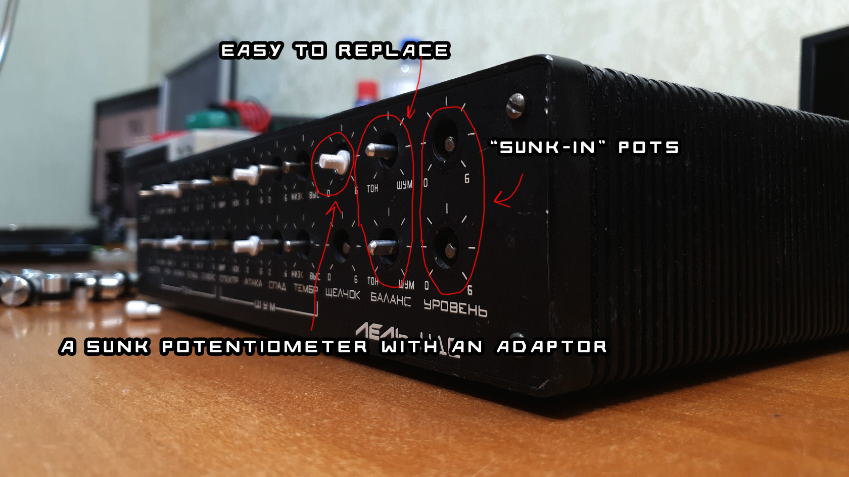
1. Potentiometer knobs. They suck: very fragile and very tight at the same time. I've replaced them all. Be careful when bying new ones: these are not standard 6mm shaft knobs, these are old-school 4mm shaft ones. I didn't find any that will fit perfectly, because some of the potentiometers are sunk into the front panel and I had to 3d-print some adapters, STL files for which you will find in the files of this project.
2. Eletrolytic capacitors. Replace them all if your synth wasn't repaired before, they won't show any signs of leakage. The capacitor value does not matter much, all of them are filtering or DC blocking capacitors, 10, 22, 33, 47uF - it does not matter. Be carefull, though: if your synth was modded or repaired earlier (if you see any non-soviet gray metal electrolytes), maybe some of tantalium capacitors were replaced by electrolytes and the value of there capacitors does matter.
3. Clean all pots. I am using CRC products for this: kontakt-40, kontakt-60 and kontakt-wl and recommend you to do the same. You can use isopropyl alcohol, though.
4. Board traces. Some of the traces were starting to become black due to corrosion. Just cover them in flux and solder.
Mods
I didn't make any complex mods like MIDI or CV control yet. What I've done:
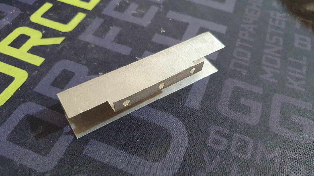
1. Replaced DIN-5 connectors with 6.3 jack. To do it I had to 3d-print some adaptors, which, again, you will find in the project files. You can just cut them from some plywood though. Unfortunatelly, after that, a shielding plate covering the outputs (shown below) didn't fit and I had to throw it away: the 6.3 jacks are a tad bit longer than DIN-5 connectors.
2. Replaced C10 and C12 to a lower value.
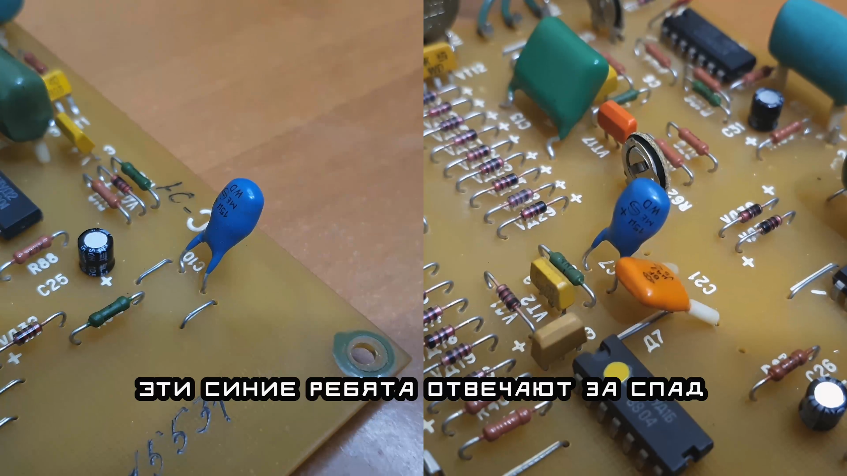
These two blue capacitors control the decay time for tone and noise envelope generators. It's way too long for me (around 6-7 seconds) at max and the precise decay time control at low values is impossible. So, I've replaced these 15uF tantal capacitors with 2.2 electrolyte ones, thus lowering the max decay by 7 times.
3. Installed second amplifier on the second board.
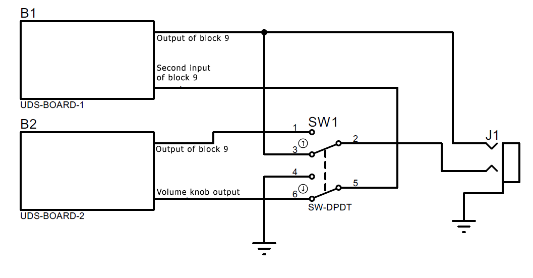 I've installed the same schematic around D14 - block 9 - on the second board to have a separate output for each channel. Of course, the output jack I've installed on the output is a stereo one. And, of course, I had to cut the wire passing the signal from channel 2 to channel 1.
You can, however, install also a DPDT switch to switch between separate and dual-mono outputs according to the schematics above.
4. Overdriven the output opamps.
Saturation and distortion are always fun! I've installed two 1N4148 diodes in parralel in opposite polarities across R109 (gain-setting resistor). Therefore, these diodes limit the output voltage to +-0.6V. This is a tad bit low, the standard is 1.2V amplitude, if I recall correctly, so I've lost 6db of volume. But, you can install 4 diodes in a "2S2P" configuration by replacing each diode with two diodes in series, thus increasing the output voltage. But, I did not like the distortion sound with 4 diodes, so I've stuck with 2. Maybe I'll add an another amplyfing cascade later.
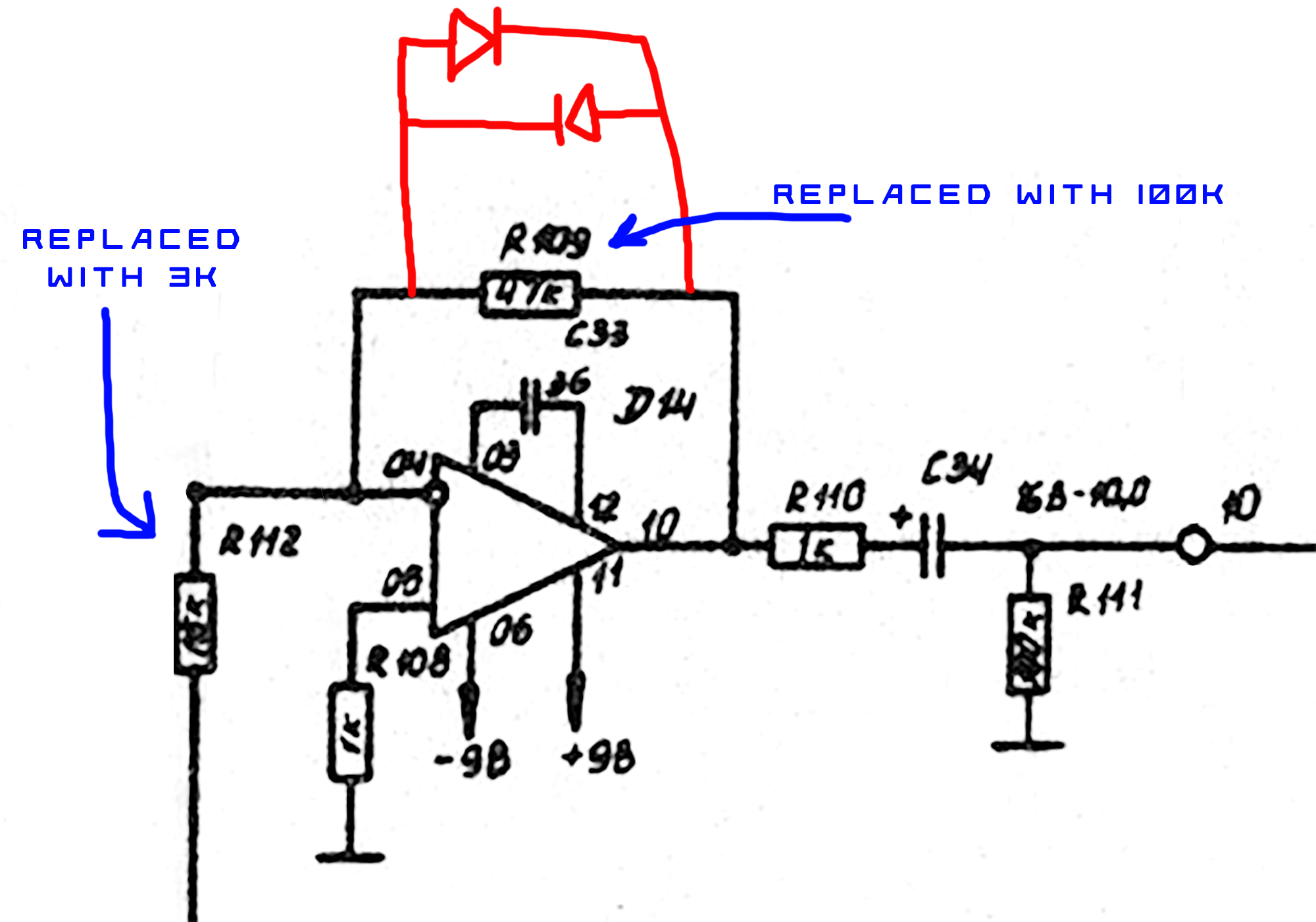
I've also replaced R112 and R109 resistors to increase the gain. It's up to taste here, I've replaced R100 (R102) with a 3kOhm one, and R109 with a 100kOhm, thus increasing the gain from 3 to 30. The signal begins to overdrive then after around 11 o'clock position of the volume knob.
5. Rack mounting
Nuff said. See the STL in the project files. You'll need to 3d-print 2 of those.
Conclusion
This is a very simple synth to mod and to repair, and it has a decent interesting sound. Considering the fact there is a ton of free space inside, you are only limited by your creativity.
Mods I didn't install yet but want to:
- CV control (probably)
- MIDI control (probably)
- Play around with the VCO, see schematics description: a saw and pulse outputs can be added. Unfortunately, there is no space on the front panel to install any additional pots or switches, but hey, that's not a problem at all.
- Add an additional output amplifier to boost the output signal a tad bit.
That's all for now. I guess now I will post here when I will make any of these mods.