It was really hot in terms of temperature at our hackerspace since our Air Conditioner basically imploded, so I did not take as many pics as I did of the first printer going together, and the ones I did take are awful in terms of quality.
On the previous printer build I did not show how I installed the glass printer bed:
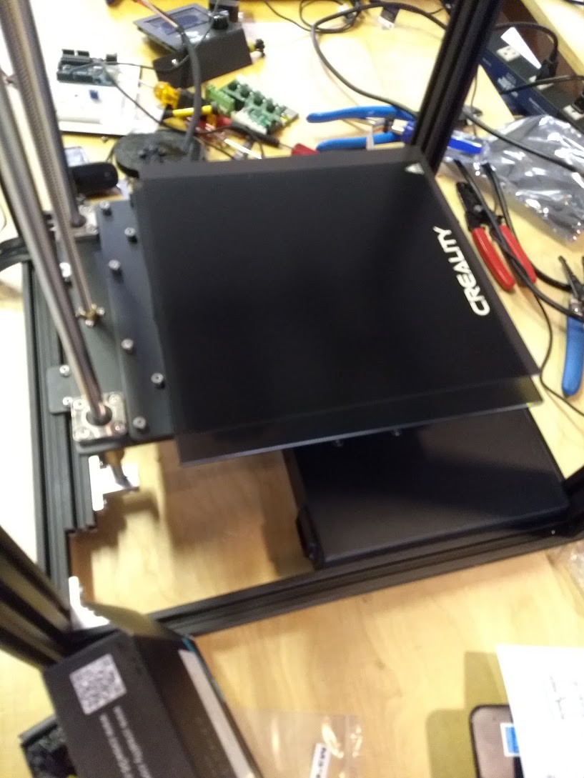
I removed the pull off magnetic bed from the top, but left the magnet surface below intact so we can use it later on if we want. I held the glass bed onto the machine using small binder clips.
We finally got the BLTouch kits in so I figured I would go about first building it into this machine, then adding it to the existing machine after I knew what I was doing.
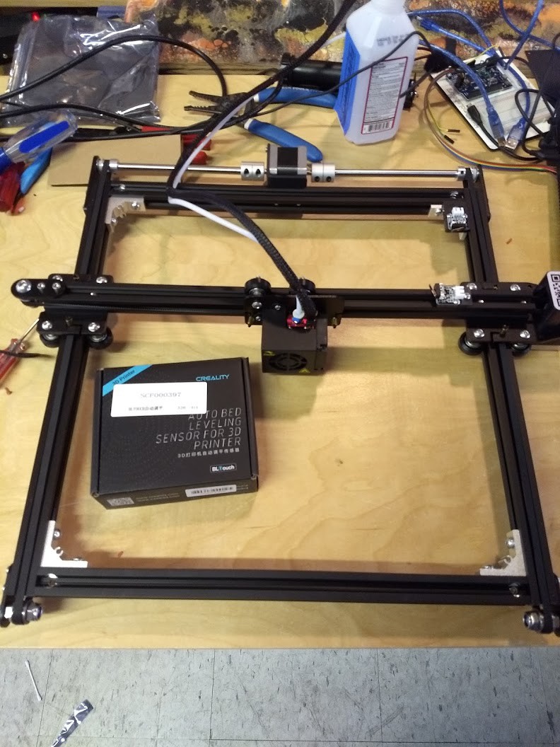
Since this printer was still being built, I decided here to take everything apart and see what I would need to do.
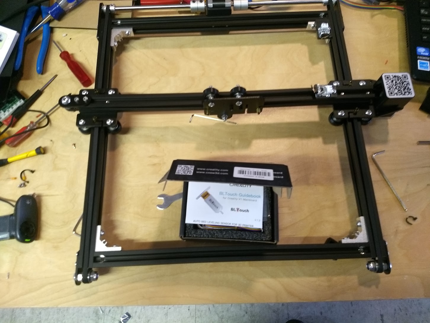
One of the nice things about the Ender 5 is how serviceable and easy to get to everything is compared to quite a few other designs of printer. This makes modification a bit easier, and if you are careful you can make sure that mods you do don't interfere with other mods, or make the printer harder to service.
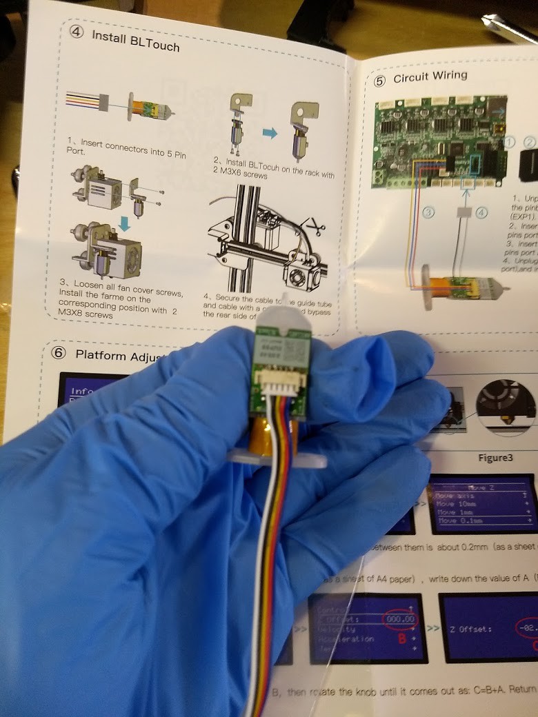
I was hoping to find a good pinout in the manual for installing this thing, but what I found instead was generalizations. This is China so I know from experience that nothing, especially pinouts, wire color, and polarity, is a given. If I don't want to blow this thing up, I must take my time here, especially since I am using a third party controller board and not their own.

So we need to do a little research now,. The White and Black wires connect to where the limit switch would go, and that seems normal. What is puzzling now is looking at the colors Blue, Red, and Yellow. When I look at the documentation for the EZBoard Lite V1.2, and other BLTouch sensors, the common color coding seems to be Brown, Red, and Yellow.

Well at least it's "close", but "close" and "correct" are two different things when you are trying to keep the magic smoke inside of a device.
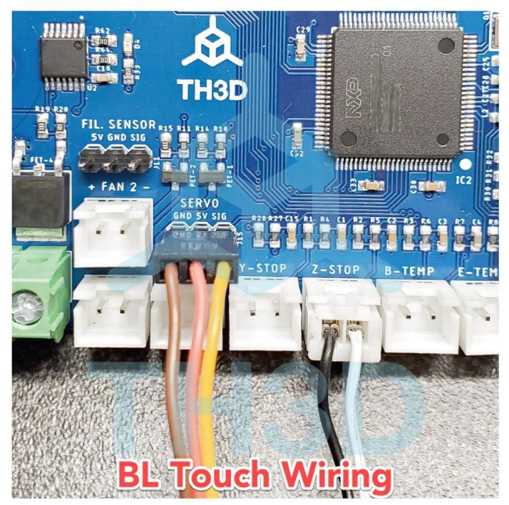
So our TH3D documentation expects Ground on the brown wire, 5 Volts on the red wire, and the Signal coming on the Yellow Wire. Looking at our stock BL Touch sensor image from the internet, we see that our wiring harness matches up except for the wire in the brown position being blue. No sweat, let's look at the connector we're to plug into the control board next.
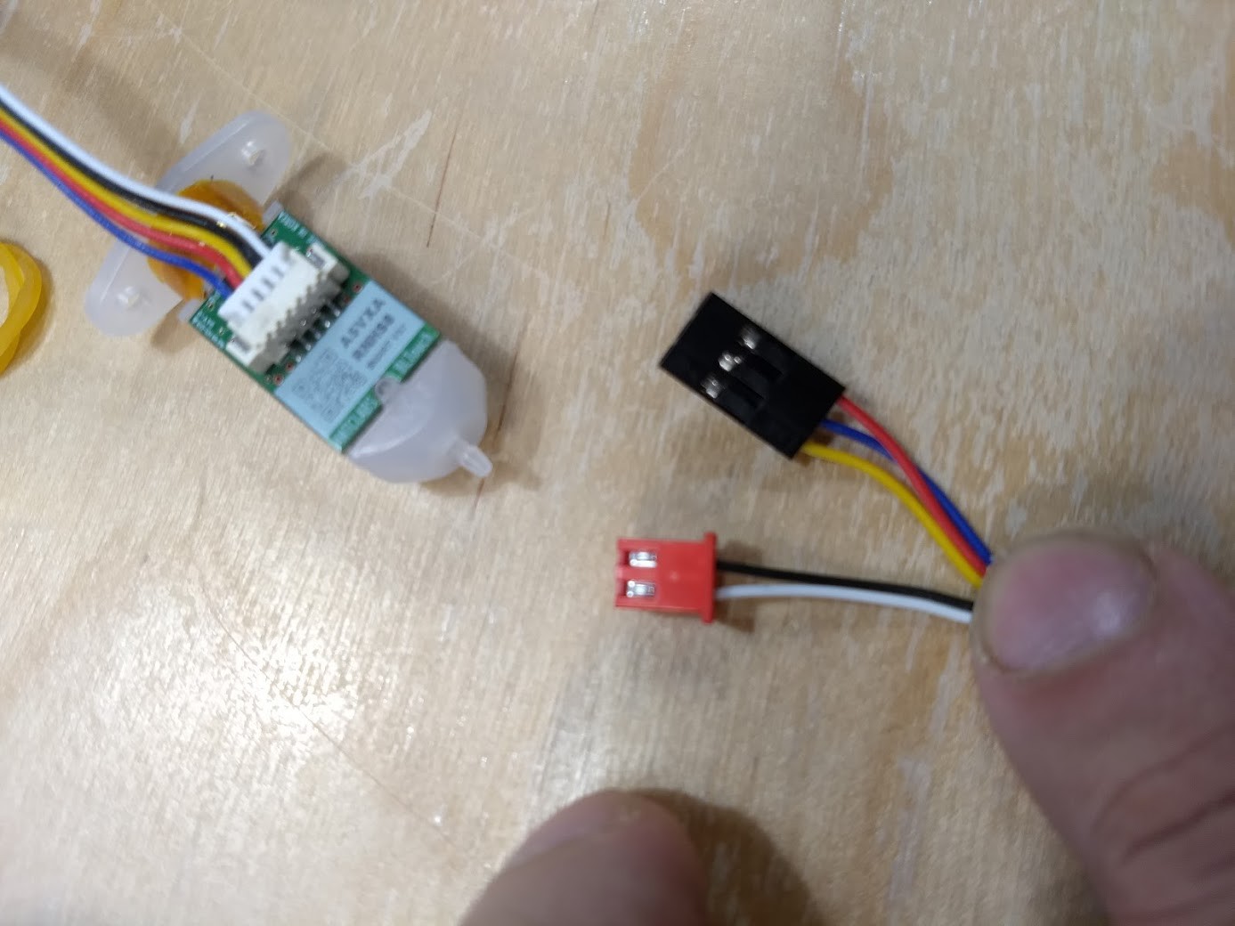
WHOAAAA THERE! That's not going to work at all. Our control board would be sending 5 volts right down the ground, and the 5 volt wire would be grounded. In other words the polarity would be reversed! I understand some newer versions of these sensors are not supposed to blow up if they are hooked up wrong, but let's not test that today!
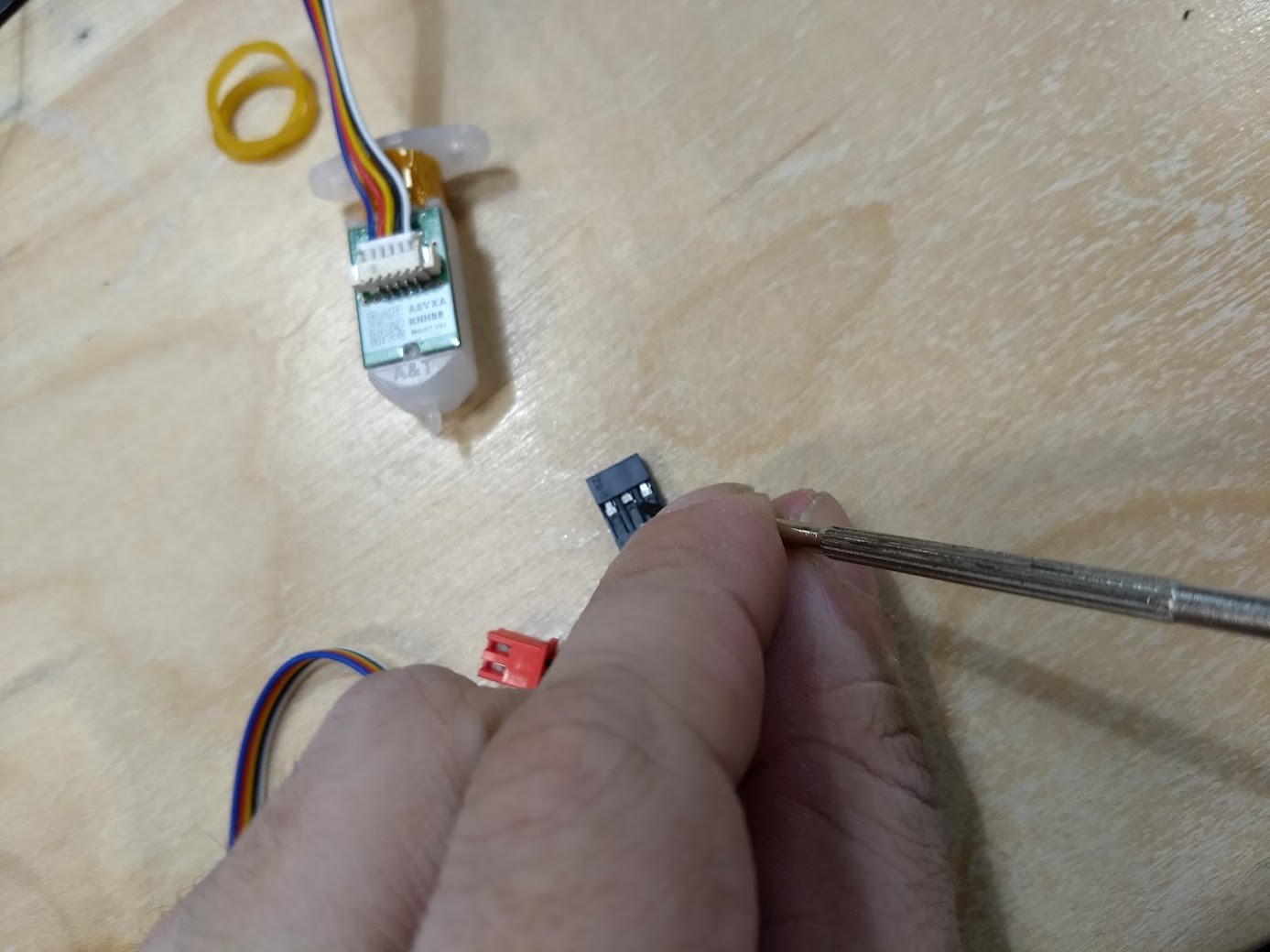
We're going to do this the wrong way and use a jewler's flathead screwdriver to extract the terminals we need to swap out from the housing by carefully and not breaking the plastic housing, or the tab holding each terminal in place.
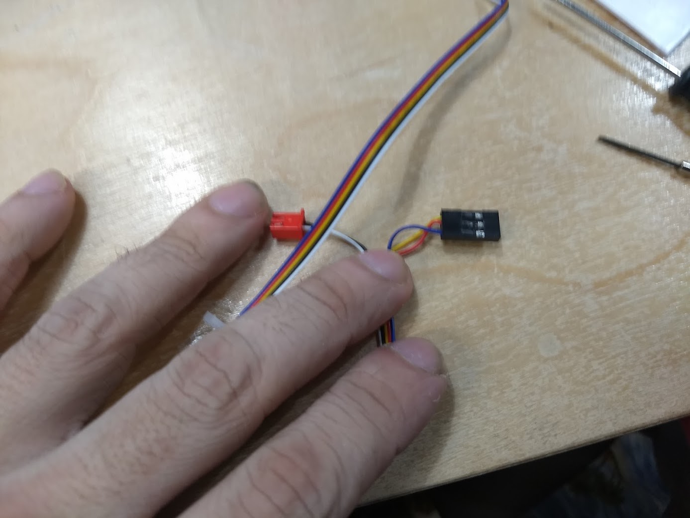
Good enough. I better make a note of this here:
If you are from Heatsync Labs looking at this post in the future and are installing the stock Creality V1.1.4 Board for some reason, do NOT INSTALL the BLTouch without swapping around the polarity on the connector!
(Also reminder to self: Add that note to the place the stock board is placed in so this doesn't happen, maybe even wrap the old control board with the note so they have to take the note off before getting to the old stock board)
I really would prefer it if I could install the BLTouch in such a way as you could remove the fan shroud/hotend without removing the BLTouch, however that's not the way this kit is set up. Perhaps that will be a thought for future builds. At least the bracket is metal, and it is pretty easy to take on/off. They do give you longer screws to hold both the bracket and the fan shroud in, so I suggest using them. I managed not to take any pictures of using Velcro and Zip Ties to affix the BLTouch wiring to the rest of the printer. I then made a quick test print to make sure everything was in order before hooking the wiring of the BLTouch to the controller board, and everything seemed to be in order.
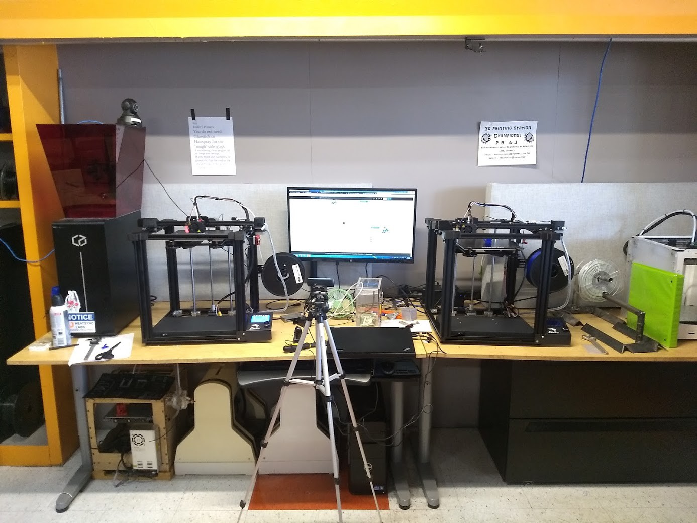
After I tried BLTouch for the first time, I was sold, so I spent extra time, fitted it to the other printer, and built a firmware up using the TH3D site just adding in the BLTouch support. Everything worked as it should, and now we have two 3D printers that offer identical results.
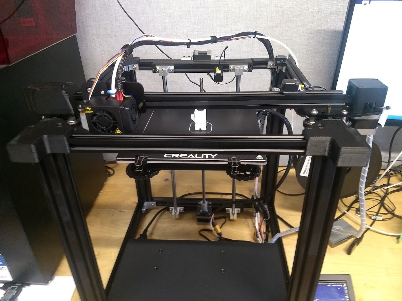
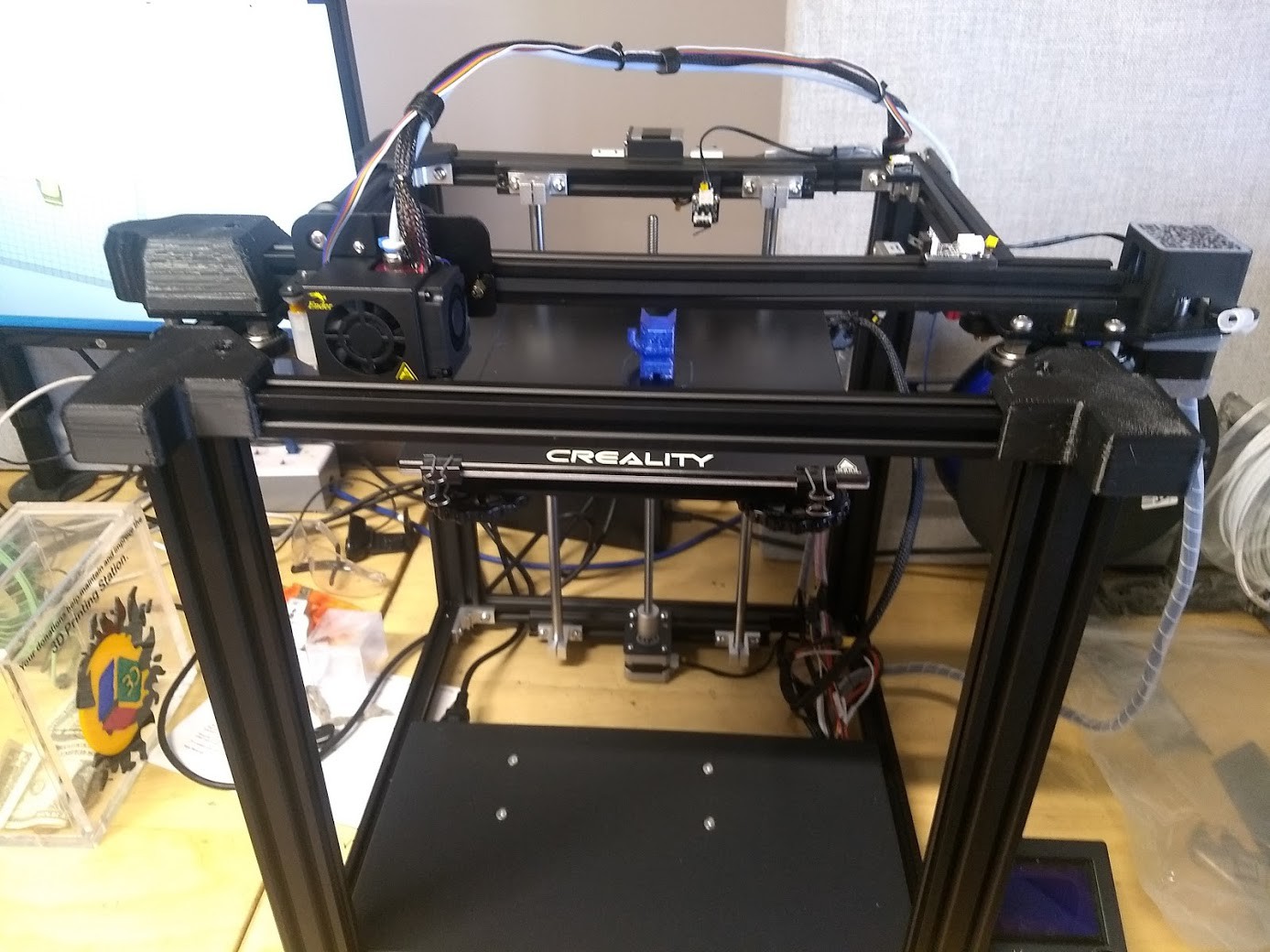
Really I can't be happier with the progress. Next up is figuring out what slicer settings are the best for the materials we have on hand, setting up the Raspberry Pi's with Otoprint, a camera, and maybe a touchscreen, possibly cutting some acrylic panels out to help with ABS work, and fitting a fan shroud to each machine to help with materials that do not enjoy the extra cooling the heatbreak fan gives them.
The shroud I found is a 2 part design (You glue the lower half to the upper half) and it bolts up where the stock blower shroud goes. I found it at https://www.thingiverse.com/thing:4262259
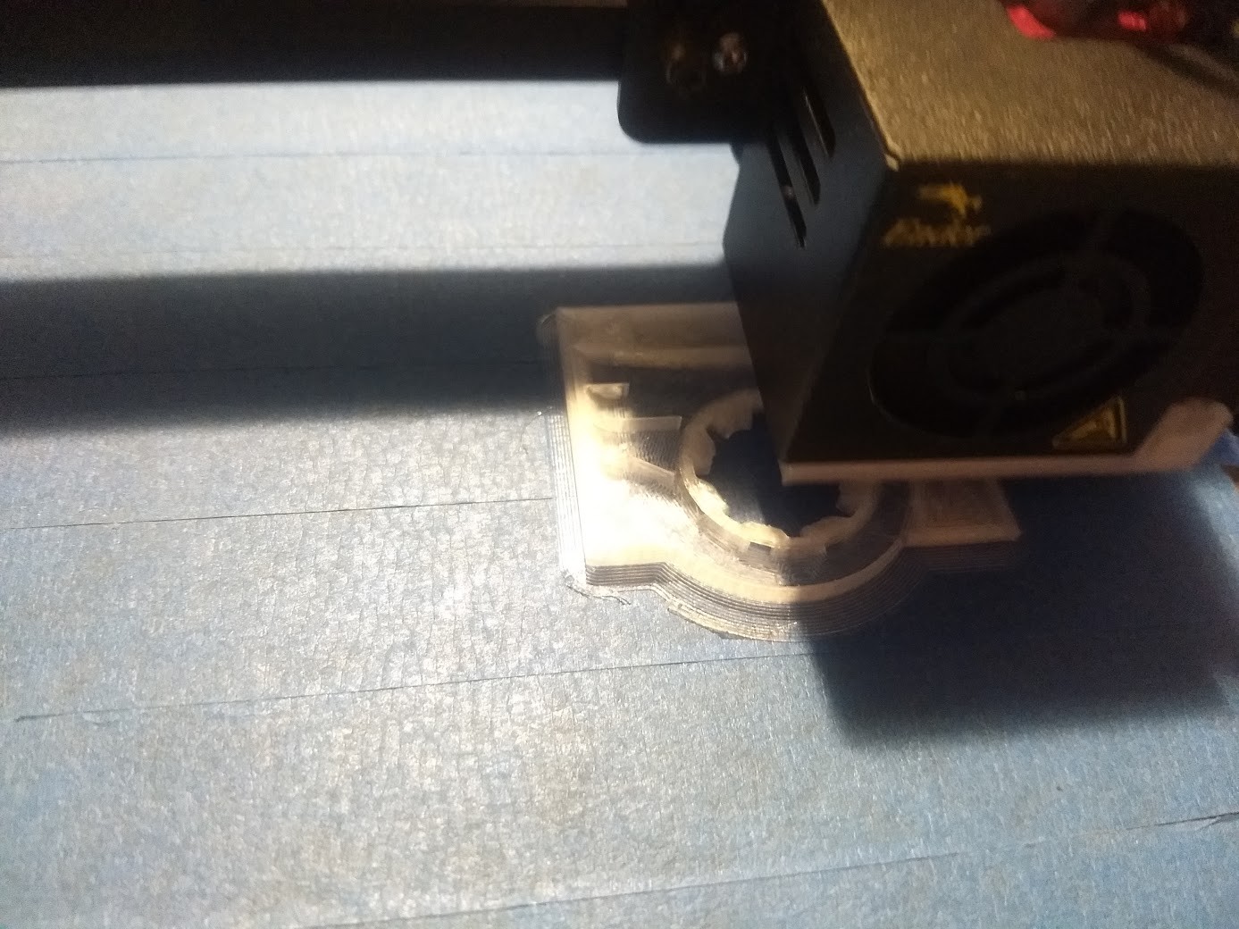
Time will tell if printing these out of PETG was a good idea. I like the two part print, as it lets me make sure the final part is of high quality and without stringing/defects that could impede the performance of the part.
I think that brings this posting up to date! Two working 3D printers, both configured the same, and all that is needed now is some tweaking and an octoprint setup to finalize them.
Edit:
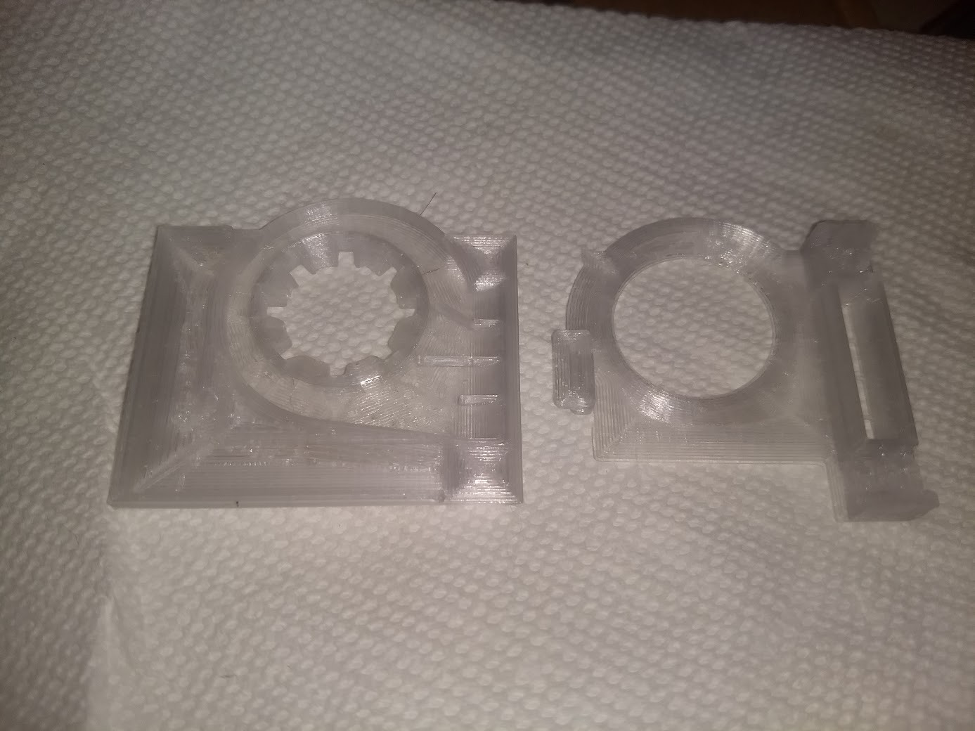
Here are the two parts of the blower shroud.
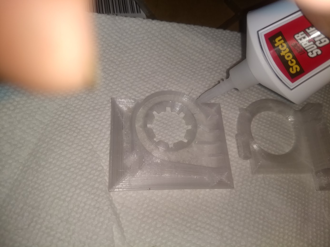
Add in some superglue on one of the mating surfaces...

Firm pressure on it for a minute or so...
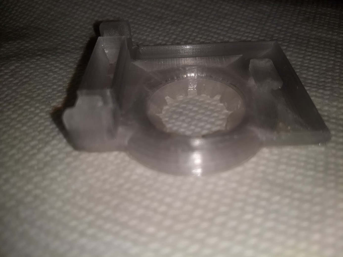
And done! Will make another one and install them on the lab printers next time I am in.
 cprossu
Discussions
Become a Hackaday.io Member
Create an account to leave a comment. Already have an account? Log In.