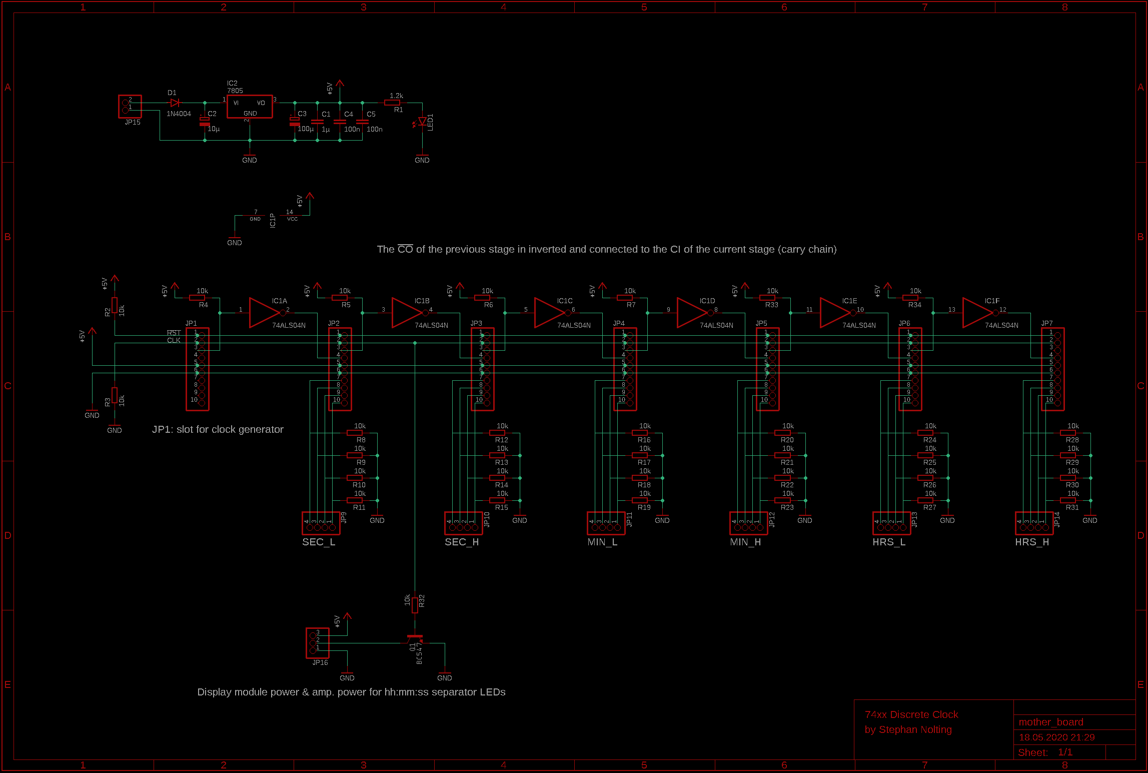
The clock module and the counter modules are plugged into the mother board. This board provides the power supply (based on a simple 7805) and takes care of the interconnection of all modules. The carry output of one counter module is connected to the carry input of the next one. Since the carry outs are low-active and the carry ins are high-active, an inverter (74HC04) is required between each stage.
The outputs from the counter modules are brought to the display board. Each output pin as a pull-down resistor to prevent the display decoders from going crazy when a module is unplugged. Also, the carry out signals are terminated using pull-up resistors.
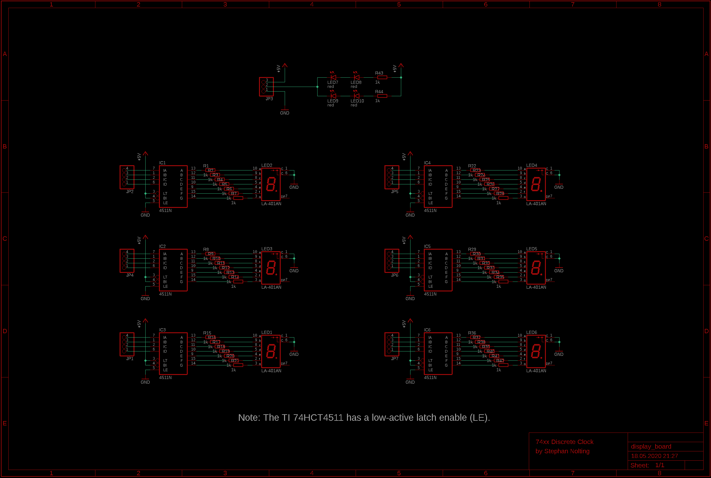
As the name already suggests, the display board carries the six 7-segment displays and the BCD-to-7-segment decoders (74HC4511). The latches of the decoders are always transparent. Also, the decoder's lamp test or output enable features are not used. There are two LEDs between the HRS and MIN displays and between the MIN and SEC display. These LEDs are driven (via a transistor on the mother board) by the main clock signal to give the clock a nice radio clock look.
Used logic chips:
* 74HC04 (mother board)
* 74HC4511 (display board)
Schematics:
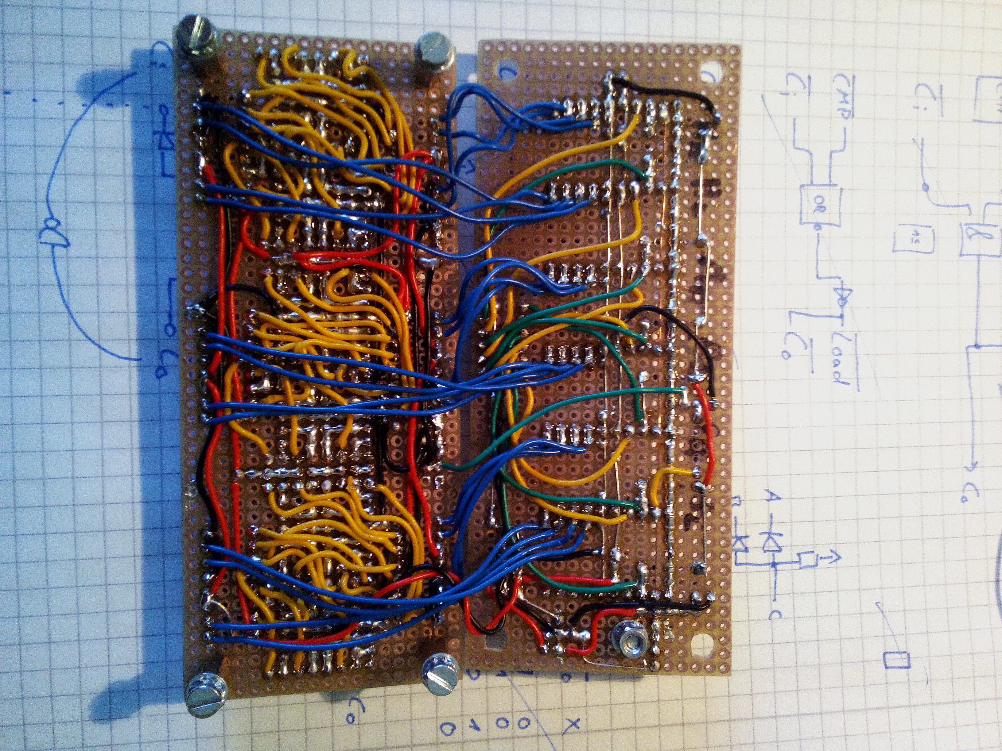
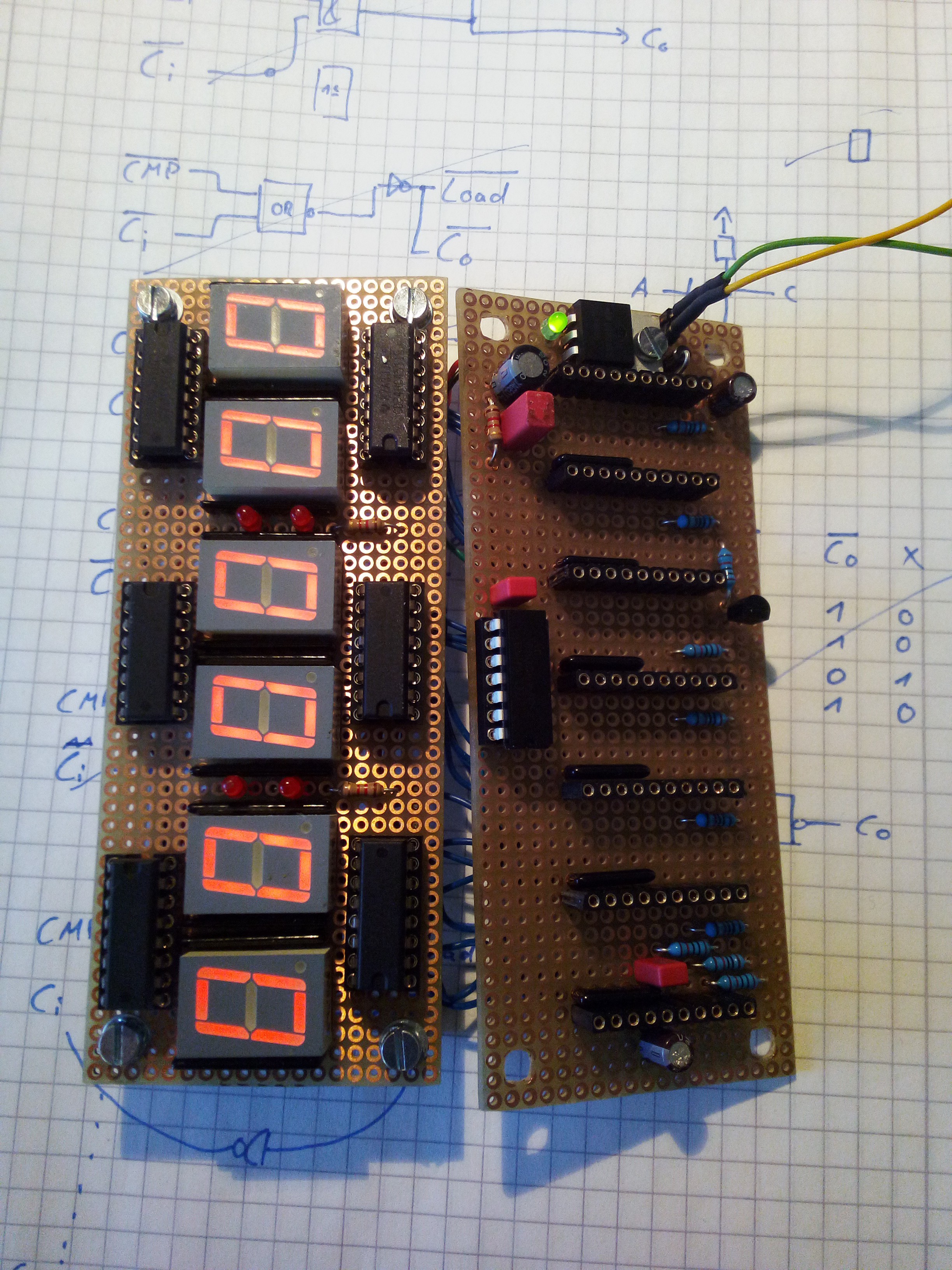
Pictures:
Discussions
Become a Hackaday.io Member
Create an account to leave a comment. Already have an account? Log In.