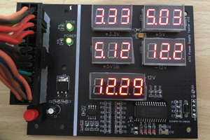
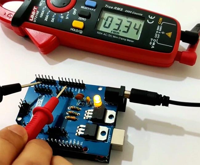
So today we will be designing a Multipurpose Power Supply. The Power Supply will be an Arduino UNO Power Supply Shield which will output multiple voltage range such as 3.3V, 5V and 12V. The Shield will be a typical Arduino UNO shield with all pins of Arduino UNO can be used along with extra pins for 3.3V, 5V, 12V and GND. Here the PCB is designed on the EasyEDA PCB Designer and manufactured by PCBgogo.
0%
0%
DIY Arduino Power Supply Shield with 3.3v, 5v and
The power supply is one of the most important part of whole project and there is always need of multiple output voltage power supply.
Become a Hackaday.io member
Already have an account? Log in.
Just one more thing
To make the experience fit your profile, pick a username and tell us what interests you.
Pick an awesome username
hackaday.io/
Your profile's URL: hackaday.io/username. Max 25 alphanumeric characters.
Pick a few interests
Projects that share your interests
People that share your interests
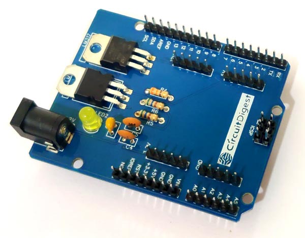
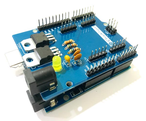
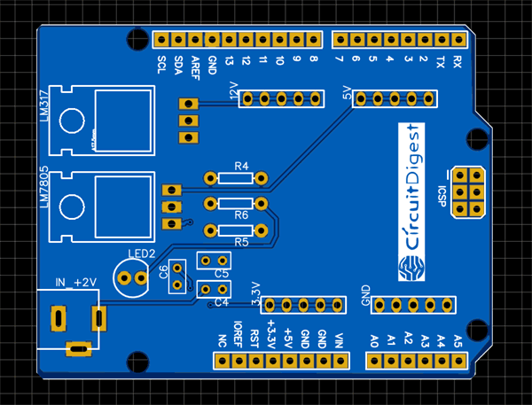 Assembling the PCB
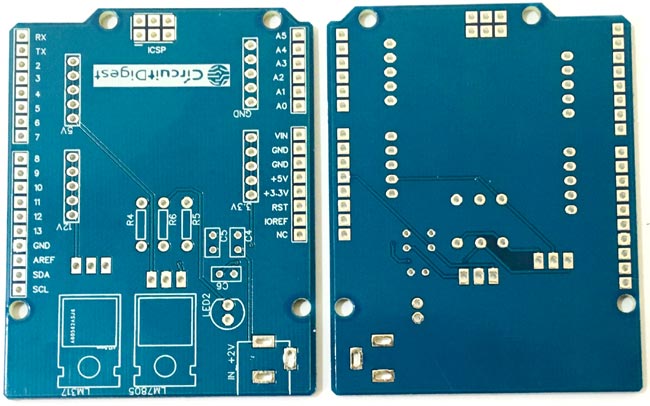
 ASHUMHRPROJECTS
 Denis
Denis