Stefan Wagner
Working Principle
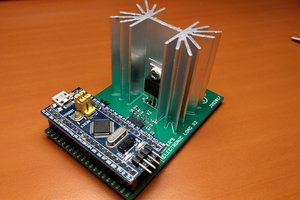
The ATtiny814 controls the electronic dummy load with its internal digital to analog converter (DAC). All of its 5 internal reference voltages are being used in order to get the maximum accuracy and resolution of the DAC. The DAC is connected to an OpAmp which acts as a unity gain amplifier controlling the resistance of the MOSFET. Voltage and current are measured via a high side 8 mOhm shunt resistor connected to an INA219 with a resolution of 4mV/1mA. A second INA219 is connected to another 8 mOhm shunt resistor between the PWR-IN and PWR-OUT terminal. The Power Analyzer is connected via USB to a PC or a RaspberryPi. Commands to the Analyzer can be sent via a serial monitor or by the GUI-based Python skript. The Analyzer has different built-in automatic test algorithms. The collected data is sent back via the serial interface/USB to the PC/RaspberryPi. The ATtiny814 constantly measures power and temperature of the heatsink. It controls the fan and cuts off the load when the temperature gets too hot.
Test Algorithms
- Using a serial monitor: Test algorithms can be started by sending the corresponding command via a serial monitor. The collected data will be displayed in the serial monitor and can be exported to a spread sheet program for further analysis.
- Using the GUI-based python application: This is the easy way. Everything should be self-explanatory. All following example pictures are created by this application.
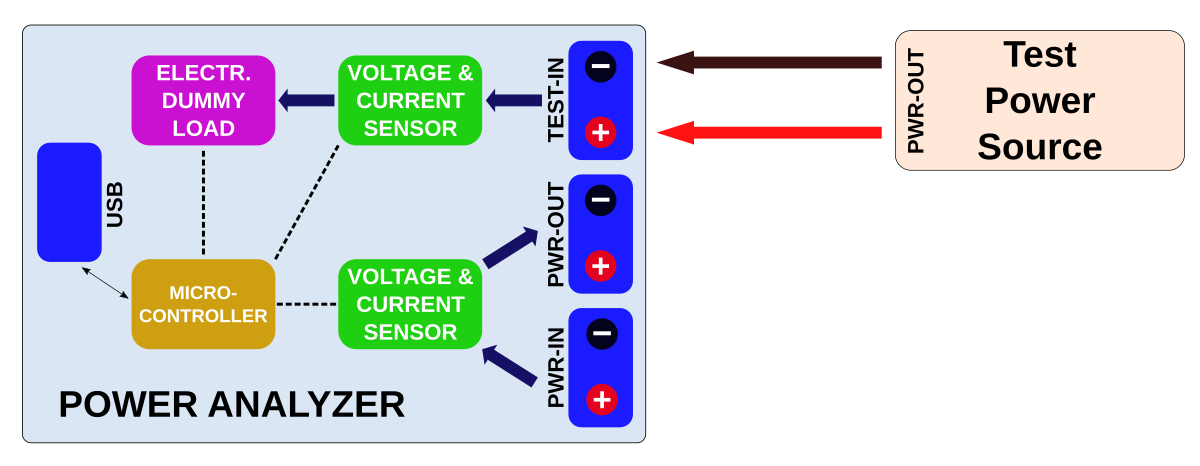
Load Test

- Command: "l maxloadcurrent[mA: 17..5000] minloadvoltage[mV: 0..26000]"
- Example: "l 2500 4200"
- The Power Analyzer continuously increases the load from 17 mA up to maxloadcurrent. It stops automatically if the voltage drops below minloadvoltage. It continuously transmits the measured values via the serial interface in the format: current[mA] voltage[mV] power[mW] (seperated by the SEPERATOR string).
Voltage Regulation Test
- Command: "g maxloadcurrent[mA: 17..5000]"
- Example: "g 3000"
- The Power Analyzer changes rapidly the load between 17 mA and maxloadcurrent. It continuously transmits the measured values via the serial interface in the format: time[ms] current[mA] voltage[mV] (seperated by the SEPERATOR string).
Efficiency Test
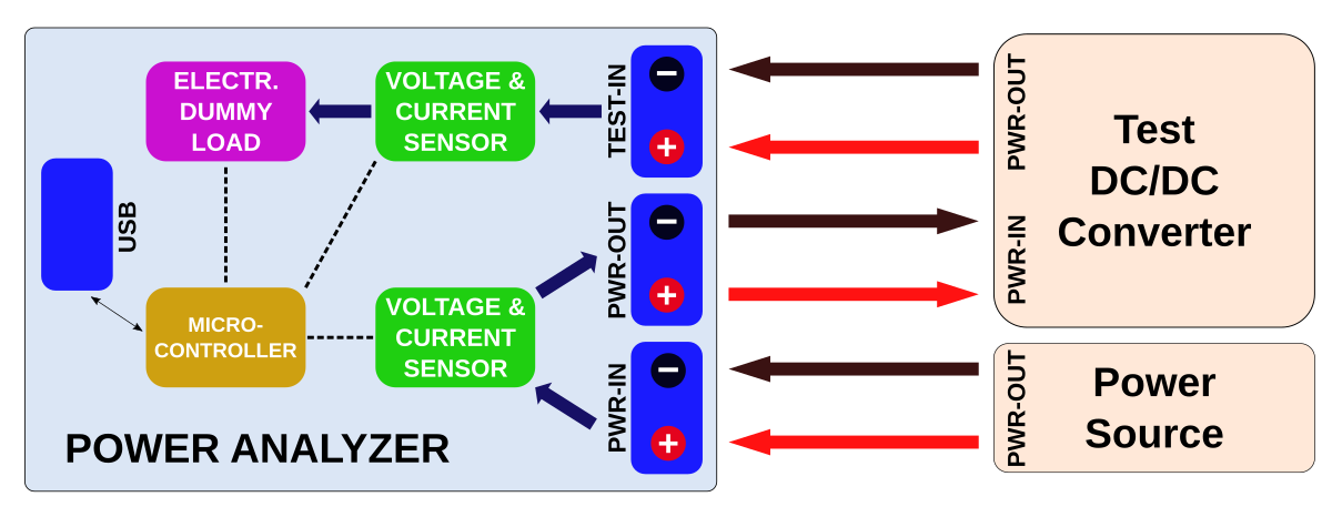
- Command: "e maxloadcurrent[mA: 17..5000] minloadvoltage[mV: 0..26000]"
- Example: "e 4000 2500"
- The Power Analyzer continuously increases the load from 17 mA up to maxloadcurrent. It stops automatically if the voltage at TEST-IN drops below minloadvoltage. It continuously transmits the measured values via the serial interface in the format: current[mA] voltage[mV] efficiency[% * 10] (seperated by the SEPERATOR string).
Battery Discharge Test

- Command: "b maxloadcurrent[mA: 17..5000] minloadvoltage[mV: 0..26000]"
- Example: "l 1000 2700"
- The Power Analyzer sets a constant current load of maxloadcurrent. If the voltage drops below minloadvoltage it constantly decreases the load to maintain minloadvoltage. It stops automatically if the load current drops to 0mA. It continuously transmits the measured values via the serial interface in the format: time[s] current[mA] voltage[mV] capacity[mAh] (seperated by the SEPERATOR string).
Long-Term Multimeter
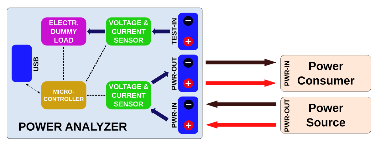
- Command: "m interval[ms: 2..65535] duration[s: 1..65535]"
- Example: "m 18000 18000"
- The Power Analyzer measures voltage, current and power delivered to the test device at every interval for a total of duration. It continuously transmits the measured values via the serial interface in the format: time[ms] current[mA] voltage[mV] (seperated by the SEPERATOR string).
Commands for Direct Control
| Command | Function |
|---|---|
| "i" | transmits indentification string ("Power Analyzer") |
| "v" | transmits firmware version number |
| "x" | terminate current test program |
| "s loadcurrent[mA]" | set load to a constant current of loadcurrent |
| "r" | reset the load to minimum |
| "t" | read current and voltage of both sensors and transmit... |
 Lithium ION
 Jasper Sikken
 Alex Fatiuk