 Stefan Wagner
Operating Instructions
Precautions
It should be noted that the test inputs do not have a protective circuit. A protective circuit would probably also falsify the measurement results. Always discharge the capacitors before connecting them to the tester! The tester can be damaged before you turn it on. Particular care should be taken when attempting to test components mounted on a circuit. In any case, the device should be disconnected from the power supply and you should be sure that there is no residual voltage.
Testing a Component
- Connect the Transistor Tester via the Micro-USB port to a 5V power supply.
- Plug the component to be tested into the socket row. Each pin of the component should have its unique socket number (1 to 3).
- Press the TEST button and wait for the result shown on the OLED display.
Characteristics
| Component | Measuring Range |
|---|---|
| Resistors | 100mOhm – 50MOhm |
| Capacitors | 35pF – 100mF |
| Inductors | 0.01mH – 20H |
| Z-Diodes | max 4.5V |
- One-key-operation
- Three test pins for universal use.
- Automated detection of NPN, PNP, N- and P-channel MOSFET, JFET, diodes und small thyristors, TRIAC.
- Automated detection of pin assignment, this means the device-under-test can be connected to the tester in any order.
- Measurement of hFE and base-emitter-voltage for bipolar junction transistors, also for Darlingtons.
- Automated detection of protection diodes in bipolar junction transistors and MOSFETs.
- Bipolar junction transistors are detected as a transistor with a parasitic transistor (NPNp = NPN + parasitic PNP).
- Up to two resistors will be measured with a resolution down to 0.1 Ohm. The measurement range is up to 50 MOhm (Megaohm). Resistors below 10 Ohm will be measured with the ESR approach and a resolution of 0.01 Ohm. Beware: resolution is not accuracy.
- Capacitors in the range 35pF (picofarad) to 100mF (millifarad) can be measured with a resolution down to 1 pF (0.01 pF for capacitors with lower capacity than 100 pF).
- Resistors and capacitors will be displayed with their respective symbol, pin number and value.
- Up to two diodes will also be displayed with their correctly aligned symbol, pin number and voltage drop.
- If it's a single diode, the parasitic capacitance and reverse current will also be measured.
- Inductances of 0.01 mH to 20 H can be detected and measured.
- A measurement of ESR (Equivalent Series Resistance) of capacitors greater than 20 nF is built in. The resolution is 0.01 Ohm. For lower capacity values the accuracy of ESR result becomes worse.
- Vloss of capacitors greater 5 nF is examined. With this it is possible to estimate its Q-factor.
 kamalkedin123
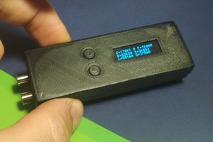
 kevarek
 engineerkid1
 John Lonergan