Stefan Wagner
Power Supply Specification Requirements
Choose a power supply with an output voltage between 16V and 24V which can provide an output current according to the table below. The power supply must be well stabilized. The current and power is determined by the resistance (R = 8 Ohm) of the heater.
| Voltage (U) | Current (I) = U / R | Power (P) = U² / R |
|---|---|---|
| 16 V | 2.00 A | 32 W |
| 17 V | 2.13 A | 36 W |
| 18 V | 2.25 A | 41 W |
| 19 V | 2.38 A | 45 W |
| 20 V | 2.50 A | 50 W |
| 21 V | 2.63 A | 55 W |
| 22 V | 2.75 A | 61 W |
| 23 V | 2.88 A | 66 W |
| 24 V | 3.00 A | 72 W |
Temperature Measurement and OpAmp Considerations
A thermocouple (temperature sensor) is located in the T12 soldering tip. It creates a very small voltage depending on the temperature difference between the hot end and the cold junction (about 22 microvolts per degree Celsius). To measure this, the heater must be switched off since both share the same connections. The low voltage is amplified by the OpAmp and measured by the ADC of the microcontroller. The LMV358 is a very cheap and versatile OpAmp, but not the ideal choice for this task because it has a fairly high input offset voltage and is quite noisy. Although the SolderingStation also works with this OpAmp thanks to the software's smoothing and calibration algorithms, I highly recommend spending a little more money in a better one. The OPA2330AIDR for instance has the same pinout and can also be used with this board. It provides significantly more accurate and stable temperature measurements.
Heater High Side Switch with N-Channel MOSFET and Charge Pump
The microcontroller switches the heater on and off via the MOSFET. Since the temperature measurement must be done over the same line and against ground, the MOSFET has to be placed between the supply voltage and the heater (high-side switch). A P-Channel MOSFET is normally used for this configuration. However, N-Channel MOSFETs usually have a lower resistance (RDS (on)), in the case of the IRLR7843 only 3 milliohms. A low resistance means a higher efficiency and a lower heat development of the MOSFET. For an N-channel MOSFET to function as a high-side switch, an additional circuit is required to maintain a positive GATE-TO-SOURCE voltage after the MOSFET is switched on. This is done using a so-called charge pump consisting of a capacitor and a diode.
Building Instructions
In addition to the components for the PCB you will need the following:
- 3D-printed case
- Aviator Plug (4- or 5-pin depending on your iron handle)
- DC Power Jack (5.5 * 2.1 mm)
- Rocker Switch (KCD1 15 * 10 mm)
- Some wires
- 4 Self-tapping screws (2.3 * 5 mm)
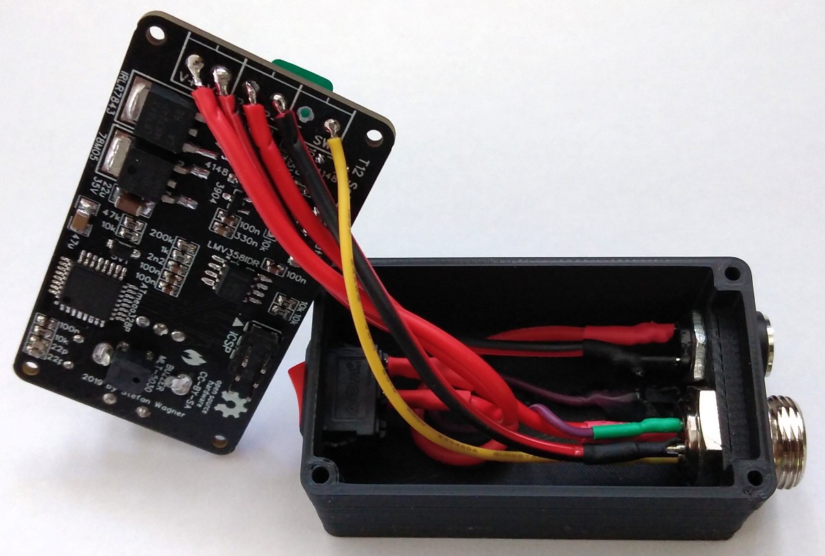
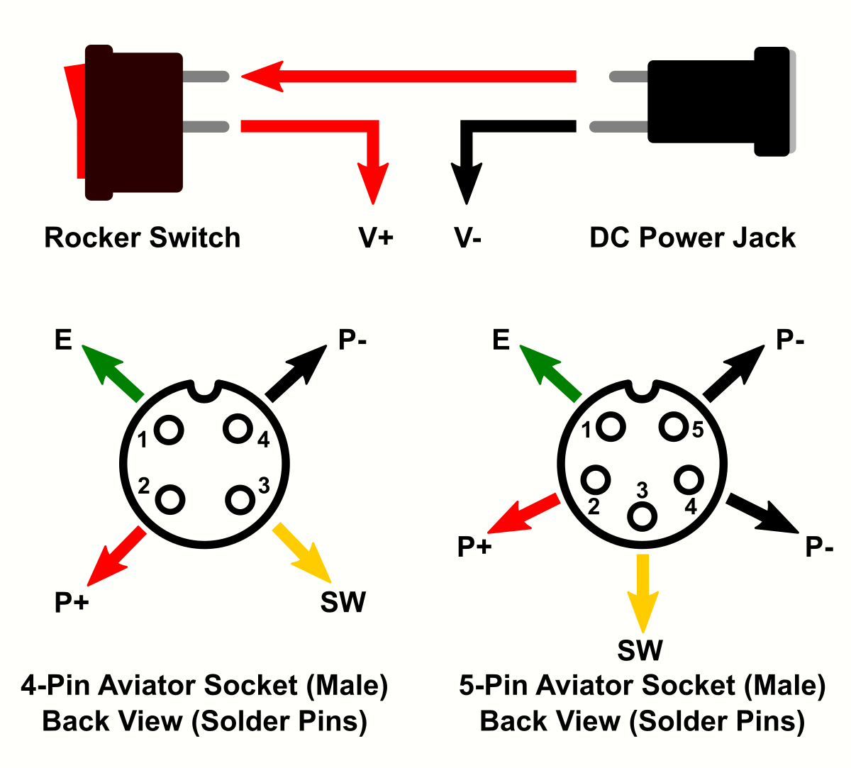
Make sure that all parts fit nicely into the case. Solder the wires to the connectors and protect them with heat shrinks. Use thick wires (AWG18) for the power connections. Make all connections according to the schematic down below. Solder the wires directly to the corresponding pads on the pcb. Upload the firmware and screw the pcb on top of the case.
 Electroniclovers123
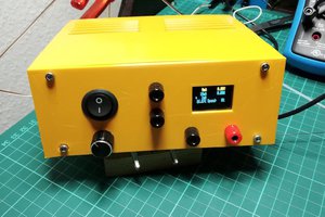
 Ringo2k
 Andrey Bykanov