VASILIS VORRIAS
-
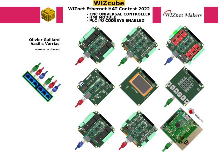
Wizcube is a Winner
05/13/2022 at 20:23 • 0 comments![]()
We are happy to announce that our WIZcube project won the SECOND PRIZE in the contest.
Thank you WIZnet.
More info on in https://wizcube.eu
-
WIZcube PCB fabrication
04/04/2022 at 12:36 • 0 commentsFour WIZcube PCBs sent for fabrication . While waiting for the delivering, the team members Olivier and Vasilis are preparing the firmware
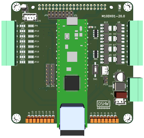
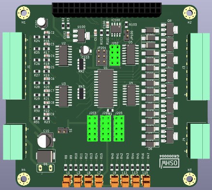
M10DX01-20 WIZcube version
WIZnet PICO clone on board
8 x Digital Opto Isolated Inputs (24V DC) plus 8 x Digital Outputs (High Side Transistor 24V DC
![]()
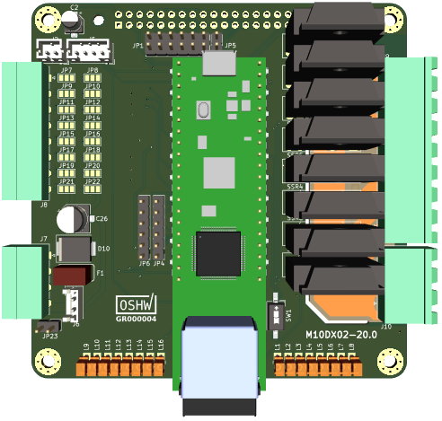
M10DX02-20 WIZcube version
WIZnet PICO clone on board
8 x Digital Opto Isolated Inputs (24V DC) plus 8 x Digital Outputs SSR (TRIAC 220V DC)
![]()
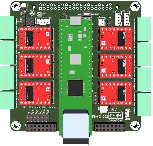
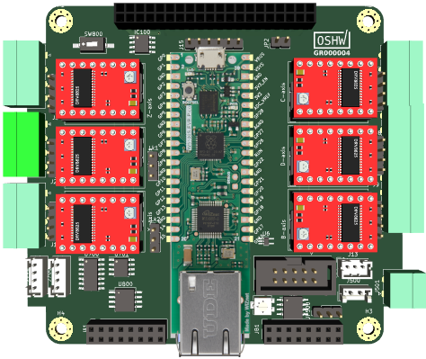
M10NC02-20 WIZcube version
WIZnet PICO clone on board
6 Axis CNC Controller. Companion modules M10DX01-20, M10HM01-20, M10RL01-20
![]()
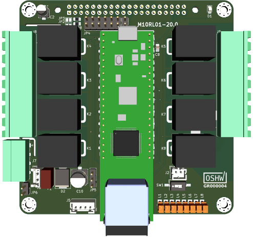
M10RL01-20 WIZcube version
WIZnet PICO clone on board
8 x Digital Outputs WizNET PICO clone (Relay 16A)
![]()
-
WIZnet WIZcube
02/23/2022 at 11:27 • 0 commentsAfter a long time working endless hours on our WIZcube project and see it submitted to WIZnet contest.
Two Makers, totally strangers between them one in Greece me and other in Denmark Olivier Gaillard teamed to go for the WIZnet contest and submit the idea before closing.
https://maker.wiznet.io/wiznet-ethernet-hat-contest/We shared the same dream to build something different. Something to be useful to the community as being OSHW project.
It is a huge project and we must finish everything until the end of March.
During the building period it will be more info on our web www.wizcube.eu![]()
-
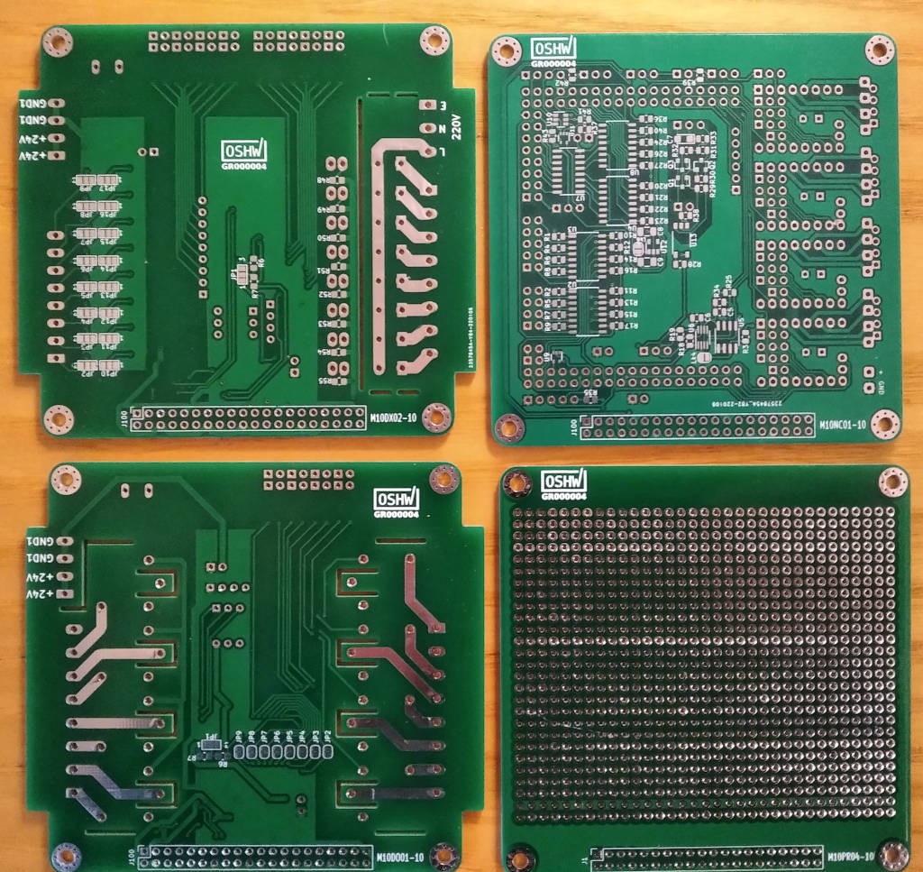
PCB ARRIVAL JAN 2022
02/08/2022 at 18:20 • 0 commentsWe received from JLCBC a batch of PCB concerning previews designs.
1 - M10CUBE NUCLEO64 CNC. PCB code M10NC01-10
https://hackaday.io/project/171770-m10cube/log/202097-m10cube-nucleo64-cnc
2 - M10CUBE I2C INPUT 8X24V, OUTPUT 8XSSR TRIAC. PCB code M10DX02-10
https://hackaday.io/project/171770-m10cube/log/202093-m10cube-i2c-input-8x24v-output-8xssr-triac
3 - M10CUBE I2C 8XRELAY MODULE. PCB code M10DO01-10
https://hackaday.io/project/171770-m10cube/log/202092-m10cube-i2c-8xrelay-module
4 M10CUBE PROTOTYPE. PCB code M10PR04-10
![]()
When populated and tested we will post the results. If all gone well, KiCAD6 designs will be published.
Meanwhile as already announced we are preparing new I/O designs with Raspberry Pico on board in place of MC23XXX chips. That is necessary to line up M10CUBE concept with the era of Edge computing in IOT market.
-
M10CUBE I2C/SPI INPUT 8X24V, OUTPUT 8XHIGH SIDE (Double I/O chips)
01/24/2022 at 16:07 • 0 commentsKiCAD6. This is an INPUT 8X24V OPTO ISOLATED, OUTPUT 8XHIGH SIDE MOSFET module name M10DX03-10. I2C or SPI interface depending of what chip is used (MCP2308 or MCP23S8) and Raspberry bus
The difference between M10DX01-10 and this module, is that XMCP23X08 chips are used here. That is more flexible design since the user can make both the INPUT and OUTPUT interdependently select able I2C or SPI.
That assumption came out of the discussion of Raspberry Pico CNC. We concluded that we need SPI for fast inputs and I2C for outputs. Since this board can serve both worlds we think that this design is more appropriate.
To add the fact that at the time of writing (24/01/2022) there is shortage of many chips MCP23S7 included. Thus users will have more options building M0CUBE interfaces
. All modules from version 10 and later are sharing the new 90x90mm PCB.
![]()
Project still in progress...
Since this interface is crucial component for a 6 Axis CNC or complicated 3D Printer controller, discussion will continue here: M10CUBE PICO CNC. A Universal Controller ?
Enjoy...
-
M10CUBE I2C/SPI INPUT 8X24V, OUTPUT 8XHIGH SIDE
01/24/2022 at 15:48 • 0 commentsKiCAD6. This is an INPUT 8X24V OPTO ISOLATED, OUTPUT 8XHIGH SIDE MOSFET module name M10DX01-10. I2C or SPI interface depending of what chip is used (MCP23017 or MCP23S17) and Raspberry bus. All modules from version 10 and later are sharing the new 90x90mm PCB.
![]()
Project still in progress...Since this interface is crucial component for a 6 Axis CNC or complicated 3D Printer controller, discussion will continue here: M10CUBE PICO CNC. A Universal Controller ?
Enjoy... -
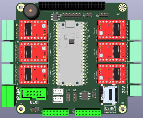
M10CUBE PICO CNC
01/06/2022 at 19:27 • 0 commentsEDIT POST 27/02/2022
This is to include the modification done for the WIZnet contest.
https://maker.wiznet.io/wiznet-ethernet-hat-contest/
The design team Olivier Gaillard and Vasilis Vorrias converted the original M10CUBE PICO CNC design to accommodate WIZnet Pico clone instead of Raspberry Pico and make WIZcube CNC we may say.
![]()
WIZcube CNC is in heavy development and soon a prototype will be in out hands
INITIAL POST 06/01/2022
This is an EXPERIMENTAL module code named M10NC02-10 designed with KiCAD6. Will be using GRBLHAL software https://github.com/grblHAL
On board Raspberry Pico.
All modules from version 10 and later are sharing the new 90x90mm PC![]()
Note the bright green 2X8 Pin Socket connector to directly connect one I/O M10CUBE module directly from optocouplers with the CPU . That way critical signals will go directly to CPU and not via I2C or SPI.
I/O modules have a Pin Header (in place of indicating LED) for interconnection between the two
One interesting feature we want to have on this design is to use the same module as a CNC Remote.
RS485 chip is on board for wired connection between modules and a UEXT (OLIMEX) connector carrying I2C, SPI, UART signals for mounting various add-ons on the remote module like Display, Rotary Knobs e.t.c.
Thea idea using an ESP-01 WiFi or a Bluetooth module for wireless communication is on the table.
Discussion will continue here: M10CUBE PICO CNC. A Universal Controller ?
Enjoy... -
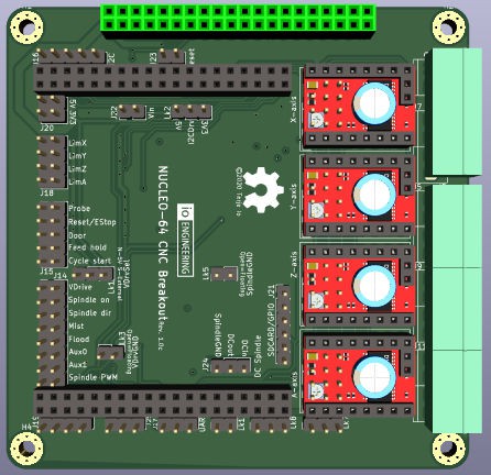
M10CUBE NUCLEO64 CNC
01/06/2022 at 19:13 • 0 commentsKiCAD6. M10NC01-10 was designed using / CNC_Breakout_Nucleo64 exact design and ported to M10CUBE platform. Is using GRBLHAL software https://github.com/grblHAL
All modules from version 10 and later are sharing the new 90x90mm PCB.
Sent for PCB fabrication in JLCPCB.
![]()
![]()
https://drive.google.com/file/d/1lqcJAB9dWVi5FL99OL5zKJ2o9BPOuXyq/view?usp=sharing
-
M10CUBE I2C INPUT 8X24V, OUTPUT 8XSSR TRIAC
01/06/2022 at 16:46 • 0 commentsKiCAD6. This is an INPUT 8X24V OPTO ISOLATED, OUTPUT 8XSSR TRIAC 16A module name M10DX02-10. I2C interface and Raspberry bus. All modules from version 10 and later are sharing the new 90x90mm PCB.
Sent for PCB fabrication in JLCPCB.
![]()
https://drive.google.com/file/d/1tZSCEnQFbMfrGkLyozYkEYEj6x9BbbHk/view?usp=sharing
-
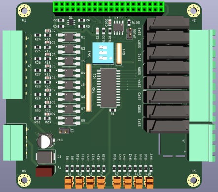
M10CUBE I2C 8XRELAY MODULE
01/06/2022 at 16:37 • 0 commentsKiCAD6. This is an OUTPUT 8XRELAY 10A module name M10DO01-10. I2C interface and Raspberry bus. All modules from version 10 and later are sharing the new 90x90mm PCB.
Sent for PCB fabrication in JLCPCB.
![]()
https://drive.google.com/file/d/19BHYOpB_LdBVpj1kuEgSROXb5tUBSk9Q/view?usp=sharing
M10CUBE
M10CUBE (M10 in short) is a modular controller box with cube dimensions 10x10x10cm. Raspberry bus will be used for the first incarnation.