 Christian Bjelle
Using a bunch of development boards and breadboards in a computer is a recipe for disaster. If you sneeze it will probably fall apart.
Also, the Mach XO2 breakout board hosts a gigantic CPLD that has a lot of resources that will just be wasted. The devices I have in my parts bin are much smaller, and are closer in size to the final resource usage. I decided to make a board for a Mach XO2 640, a W65C02S, 65C21S, 32k RAM and a serial 8k EEPROM. The Mach XO2 256 has the same pinout as the 64, but a few less IO-pins. By fitting a 74LV165 for the keyboard input, and assuming that a 65C21 would not be fitted in 256-board, the design could be adapted to accommodate the smallest Mach XO2 family member. That is, on the board and IO-wise. As it turned out, there weren't enough memory inside to support the video I needed, neither font ROM nor character ram, so only the 640 can be used. (I also forgot to buy any 74LV165)
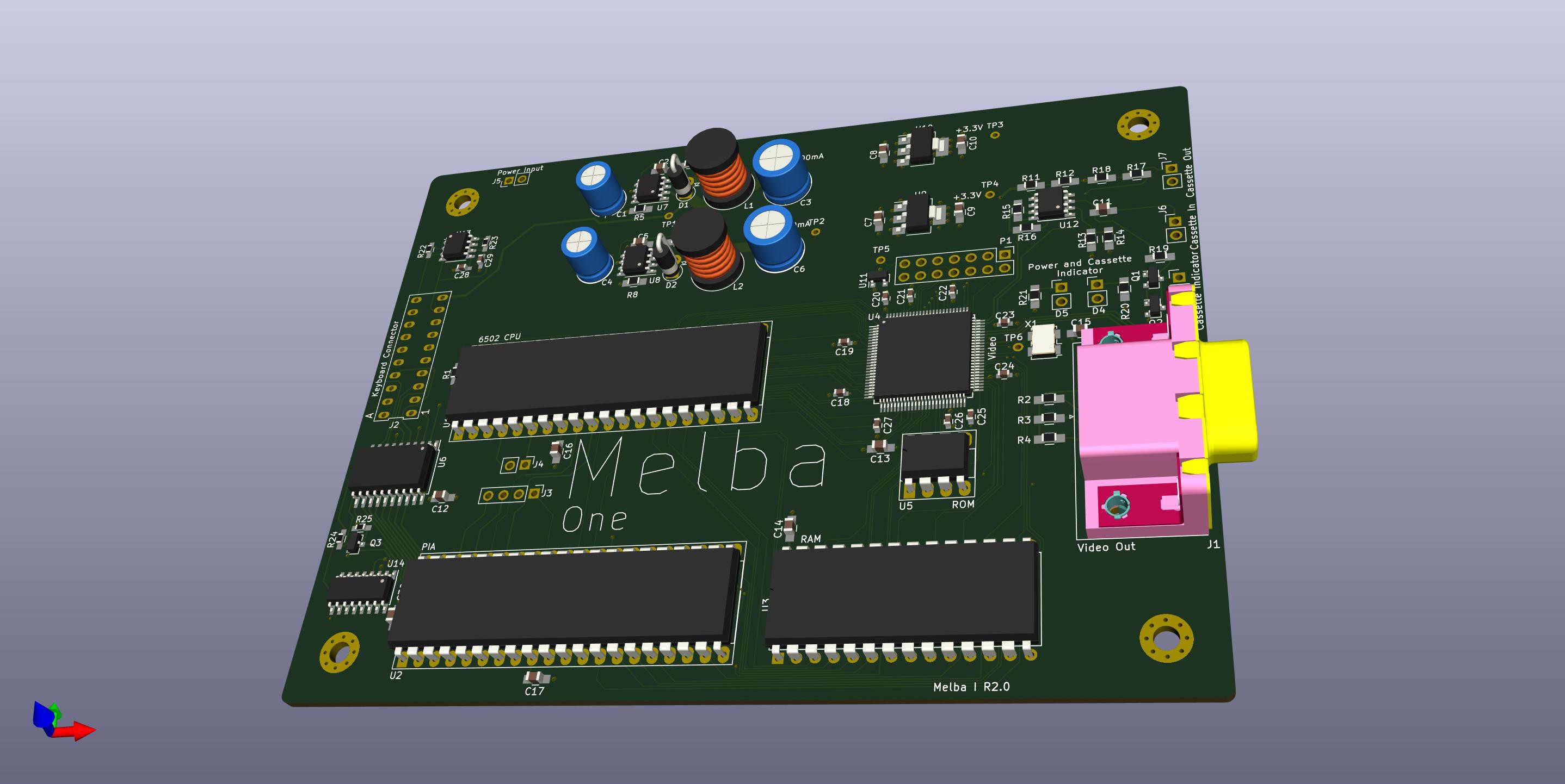
I started assembling the power supply parts. The power supply needs to have a -12V rail and a +5V rail for the keyboard. The -12 is also used for the cassette interface. These are made from jelly bean switcher parts, the MC34063, so that a simple wall wart can supply the power.
There are also two separate 3.3V regulators fed from the +5. There is really no need to have two, but I wanted to split the load between two regulators to keep the heat down, since I had no idea about how much power the system would use under full load.
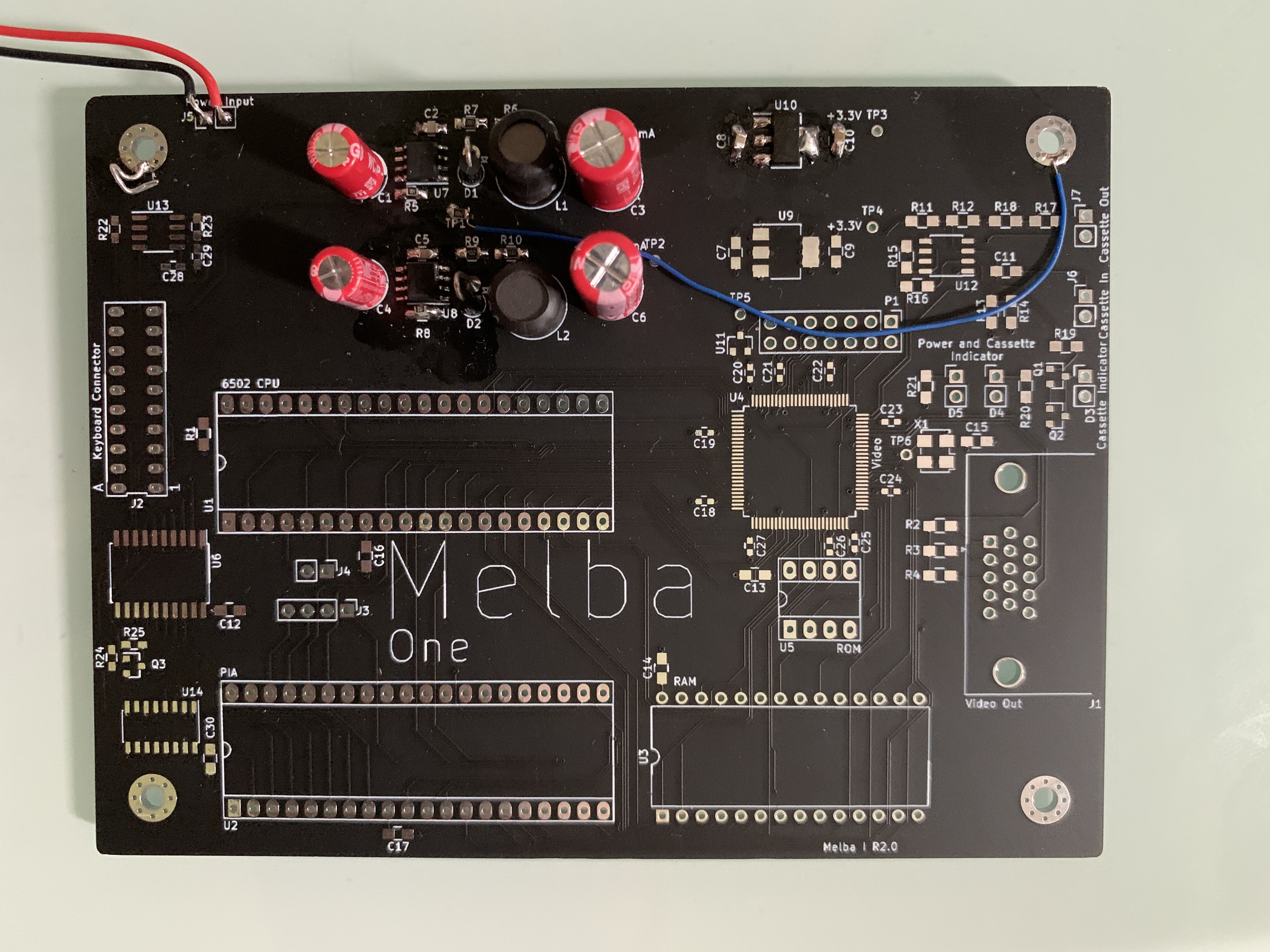
Sadly, the switching parts did not work as expected, which may have something to do with me forgetting to buy 0805 0.2Ω (and 0.7Ω) resistors, and trying to bodge them together by stacking six 1.2Ω 0603 in their place.
The -12V rail got very weird positive pulses on the output, and the +5V rail didn't oscillate properly, despite hacking on some load.
I abandoned that board, and assembled a second board without the power supply part with the intention of going back and dig deeper into what was wrong.
When the second board was assembled, I discovered that my Lattice device programmer was missing. Buying a new one is a proven method for finding a missing item, but has so far failed this time.
Since I really needed to program the CPLD on my new board, I had to find another way.
Another development board to the rescue!
The MachXO2 breakout board has a built-in JTAG programmer, and all you have to do is to disconnect the CPLD on that to be able to use it as a stand-alone programmer.
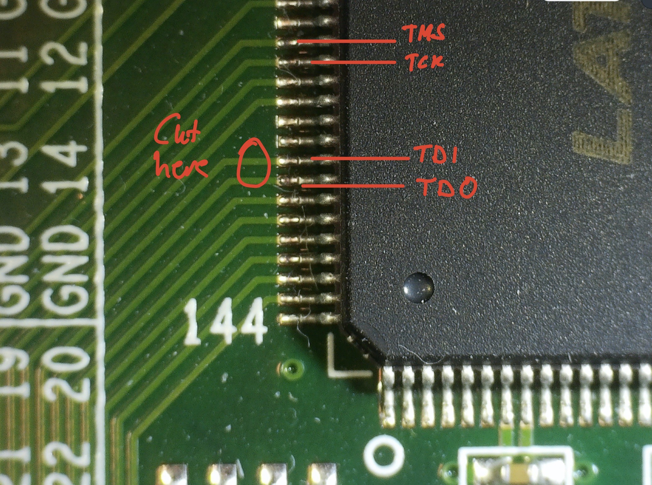
I carefully cut the TDI and TDO traces, soldered in a pin-header in the J1 position, added jumper wires to my fresh board and was ready to go!
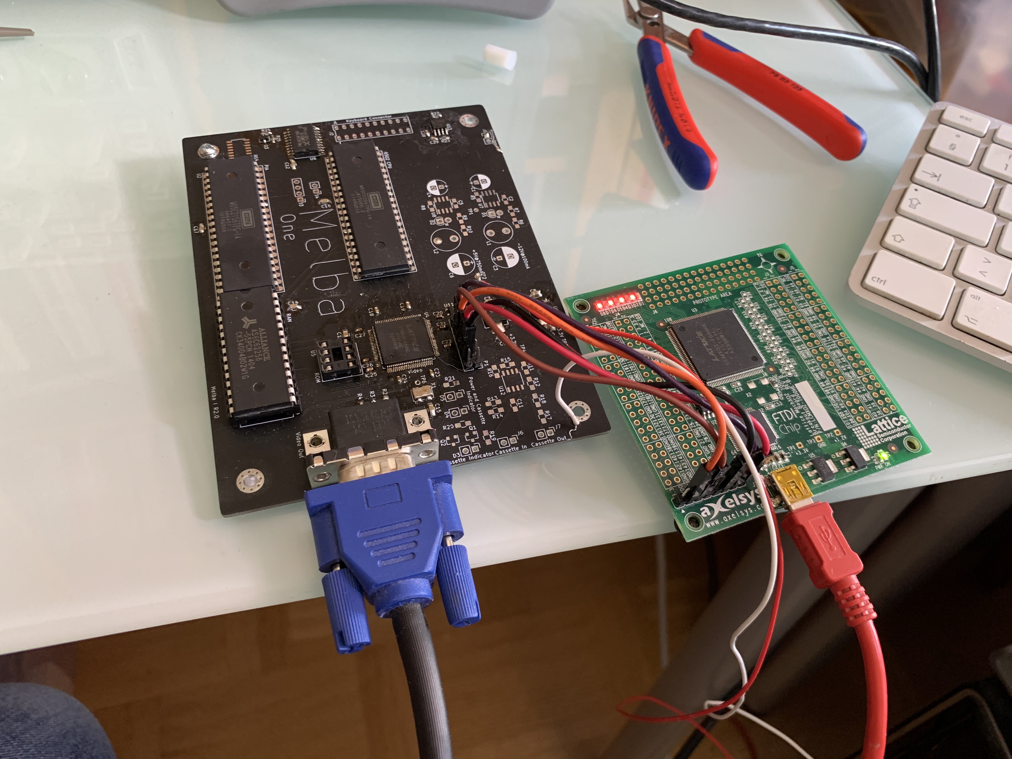
The breakout board is still showing off its blinking-led demo.
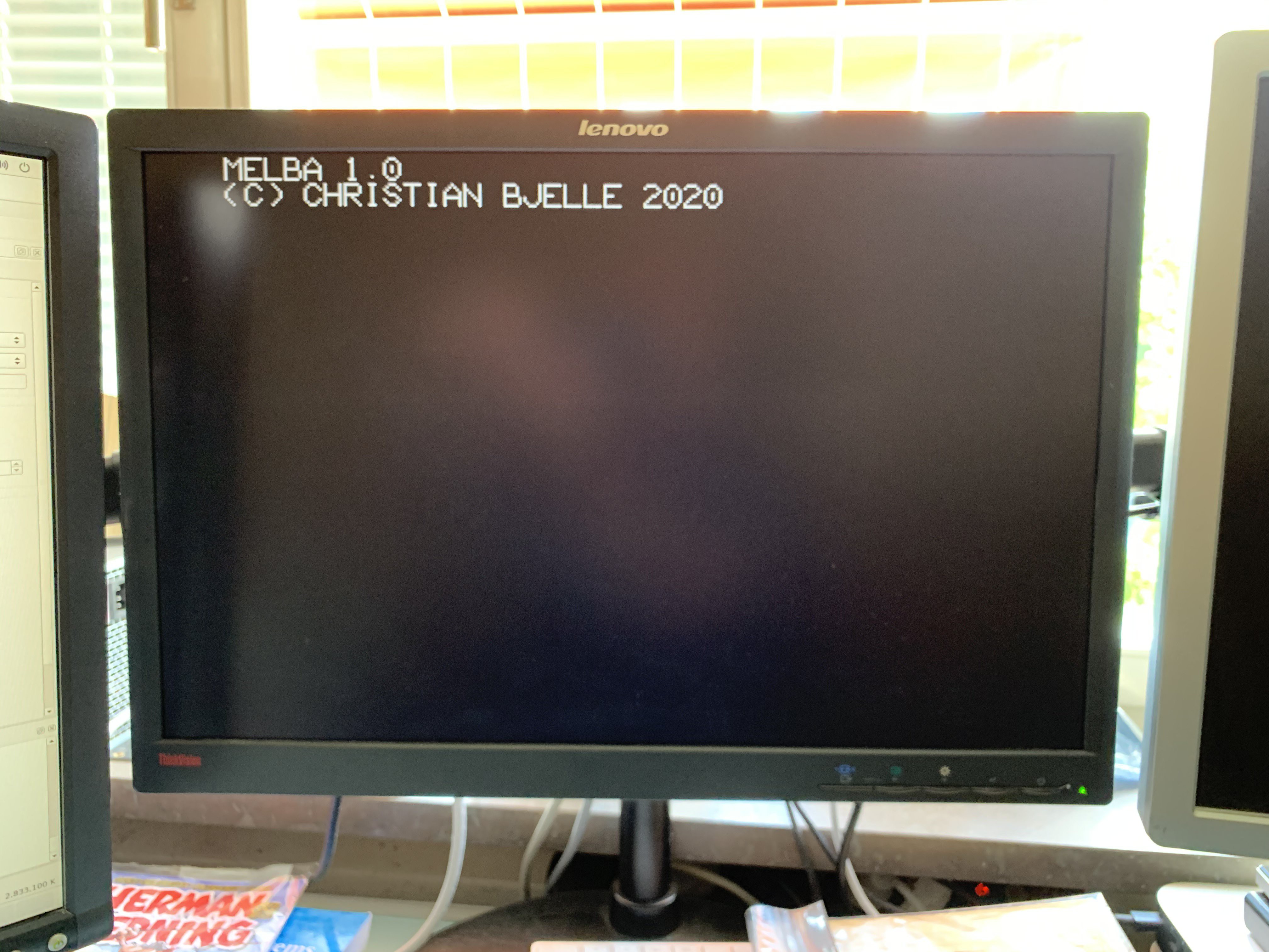
The setup worked surprisingly well, and after bodging a +5V wire to the VGA-connector to wake up the monitor, I had working video out! (again)
Discussions
Become a Hackaday.io Member
Create an account to leave a comment. Already have an account? Log In.