 Riccardo Pittini
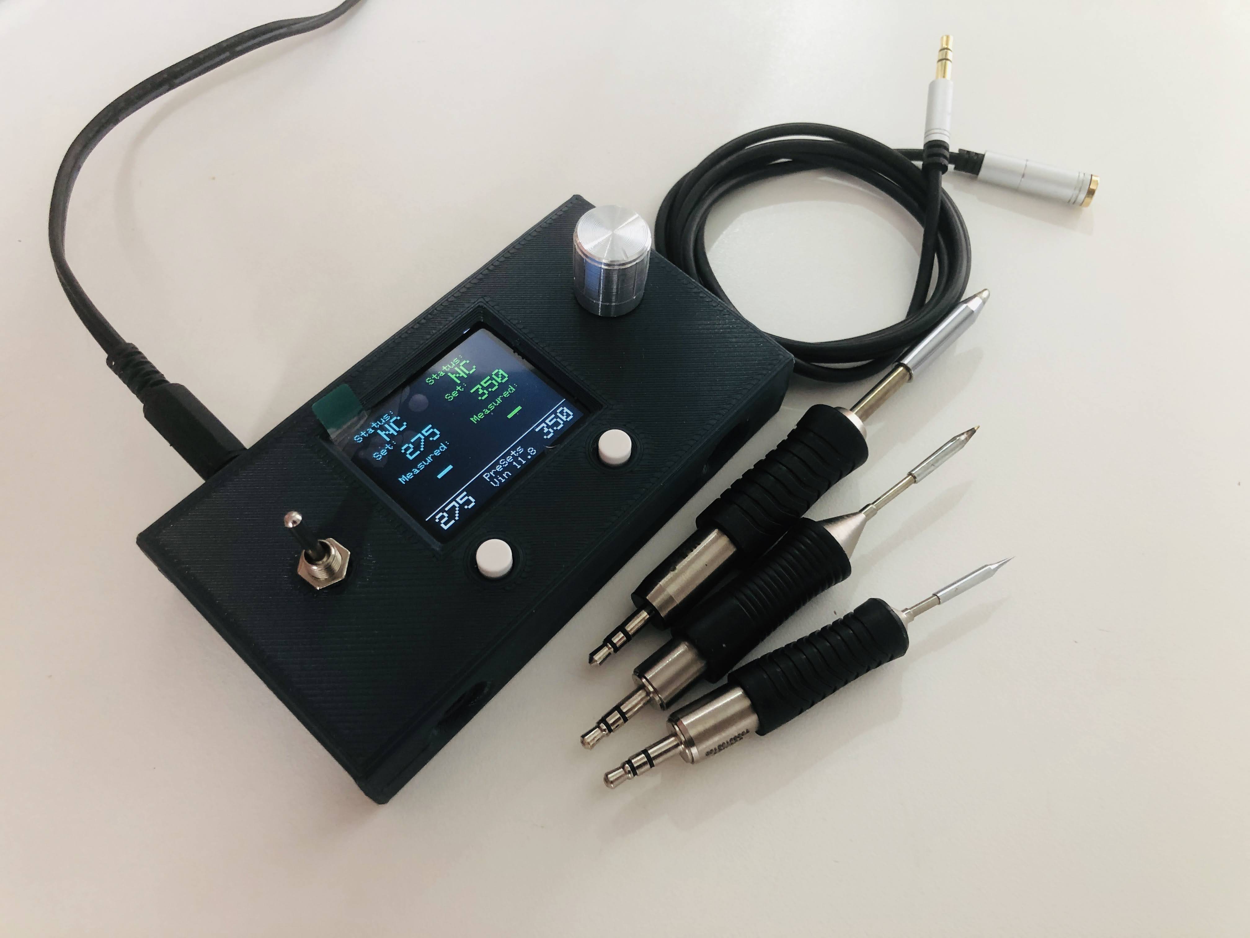
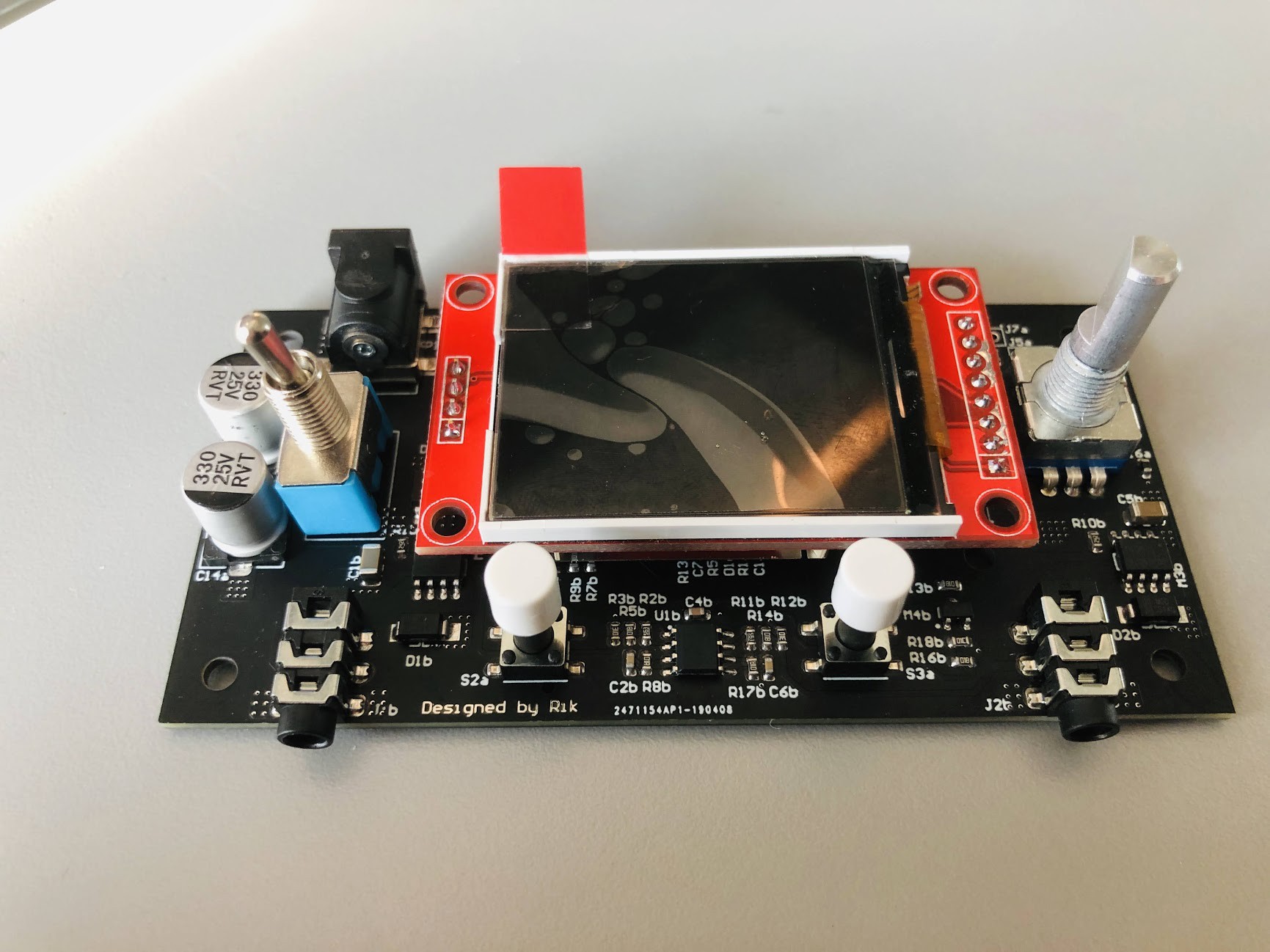
Universal Soldering station compatible with RT tips and SMD tweezers:
Tips supported:
- RT Micro
- RT Pico
- RT Ultra
- SMD tweezers
Main features:
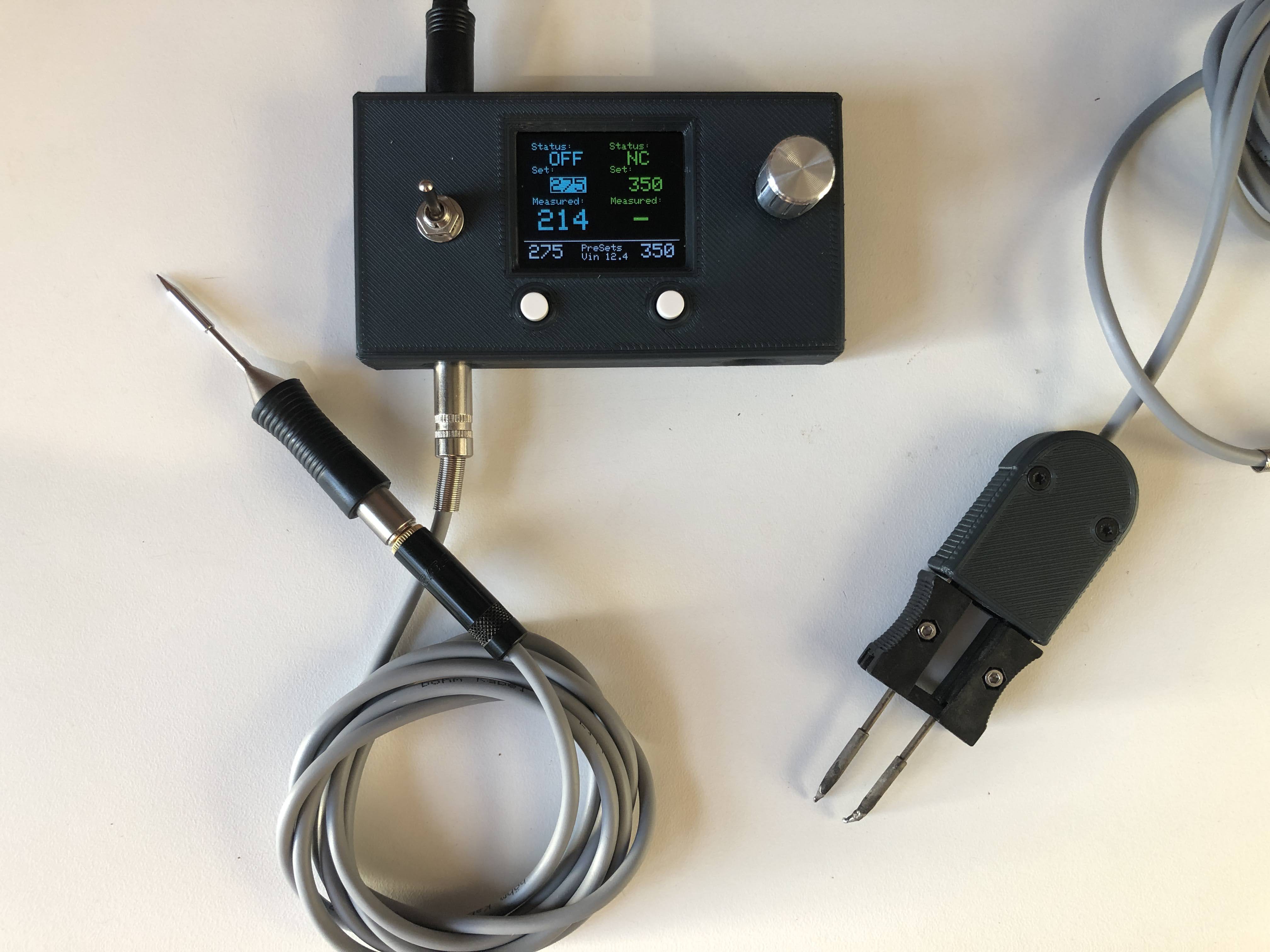
- Two independent channels
- 1.8" TFT full color LCD
- Hardware mosfet support more than 10A continuous!! (repetitive peaks of more than 50A)
- Easy to use and portable
- Compatible with Weller RT1
- Open source
- Fully Programmable (temperatures 150-450C, preset temperatures, power limitation to use various power supplies), also serial interface and source code available.
- Under Voltage Lock Out (UVLO) functionality
- Runs on standard external 12V power adapter (voltage range 7-24V), with also duty cycle limitation (allows to use smaller power supplies)
- Can run also on batteries (7-24V) with Under Voltage Lock Out (perfect for Lipo batteries!
Source code is developed based on Arduino. Full source code and manual are available in GitLab ( Source code and manual )
The case is designed to be 3D printed, two parts in a single print with no support (PLA, PETG, ABS, what you like). For a fast print it is possible to use a 0.3mm layer height (a complete case print can be done in less than 2h at 60mm/s).
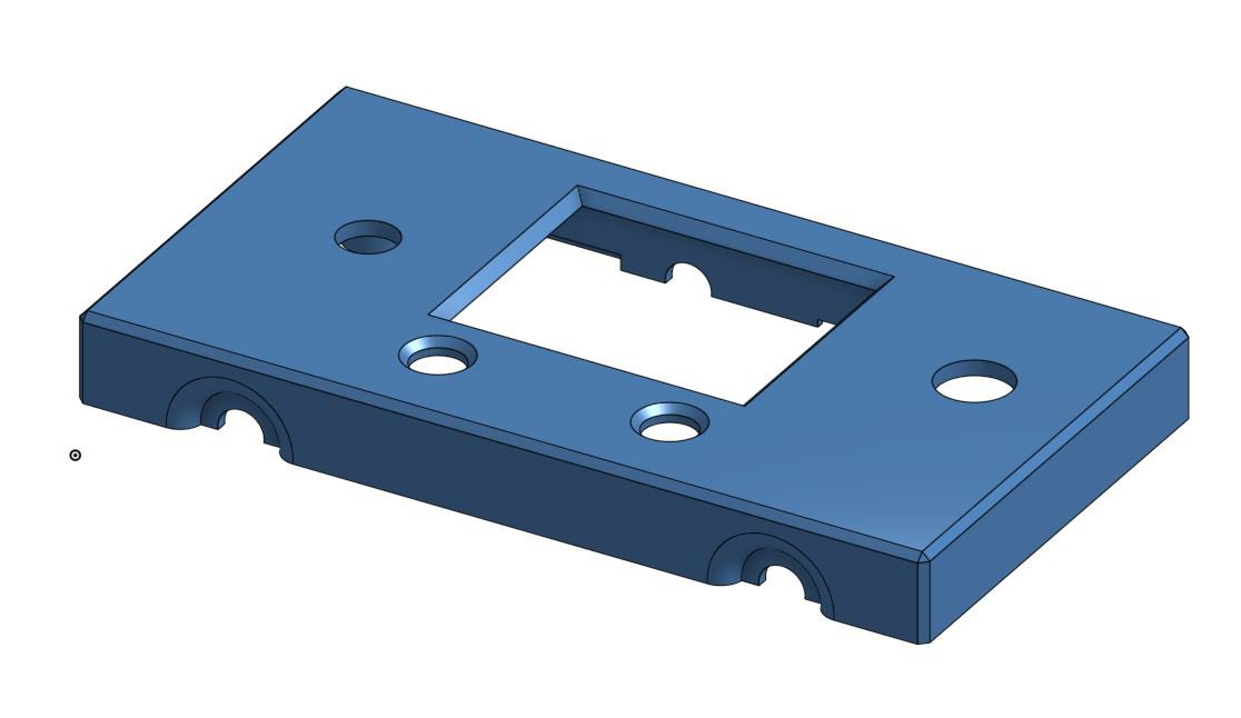
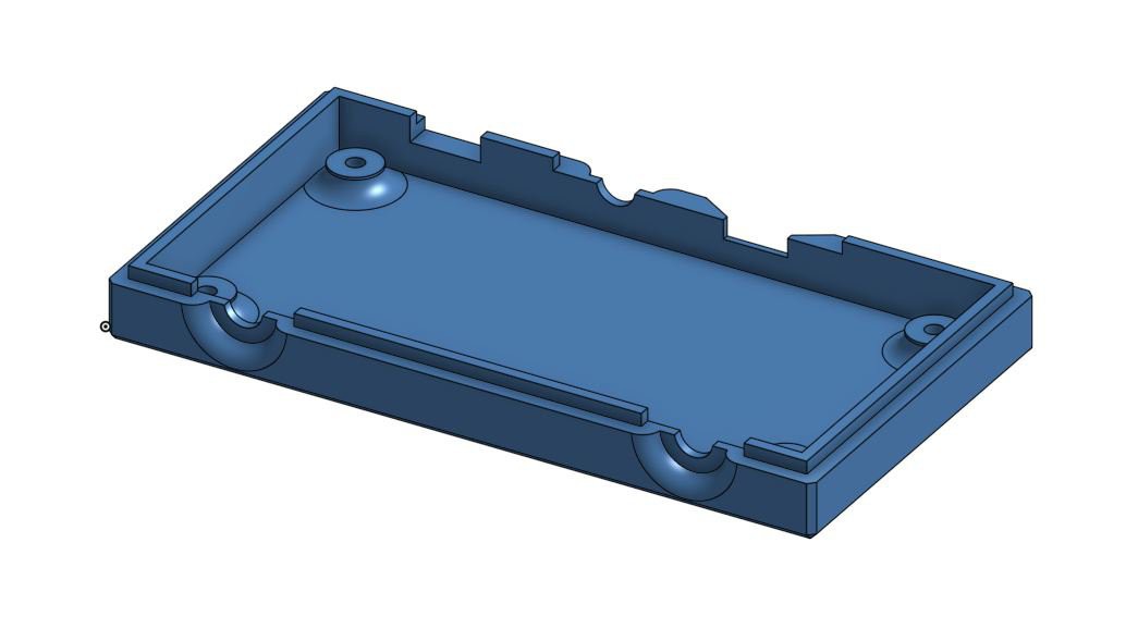
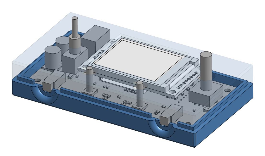
Electronics are designed to be one side SMD and with as few through home components as possible.
Underneath the TFT there is the microcontroller (AtMega 32U4) and auxiliary electronics.
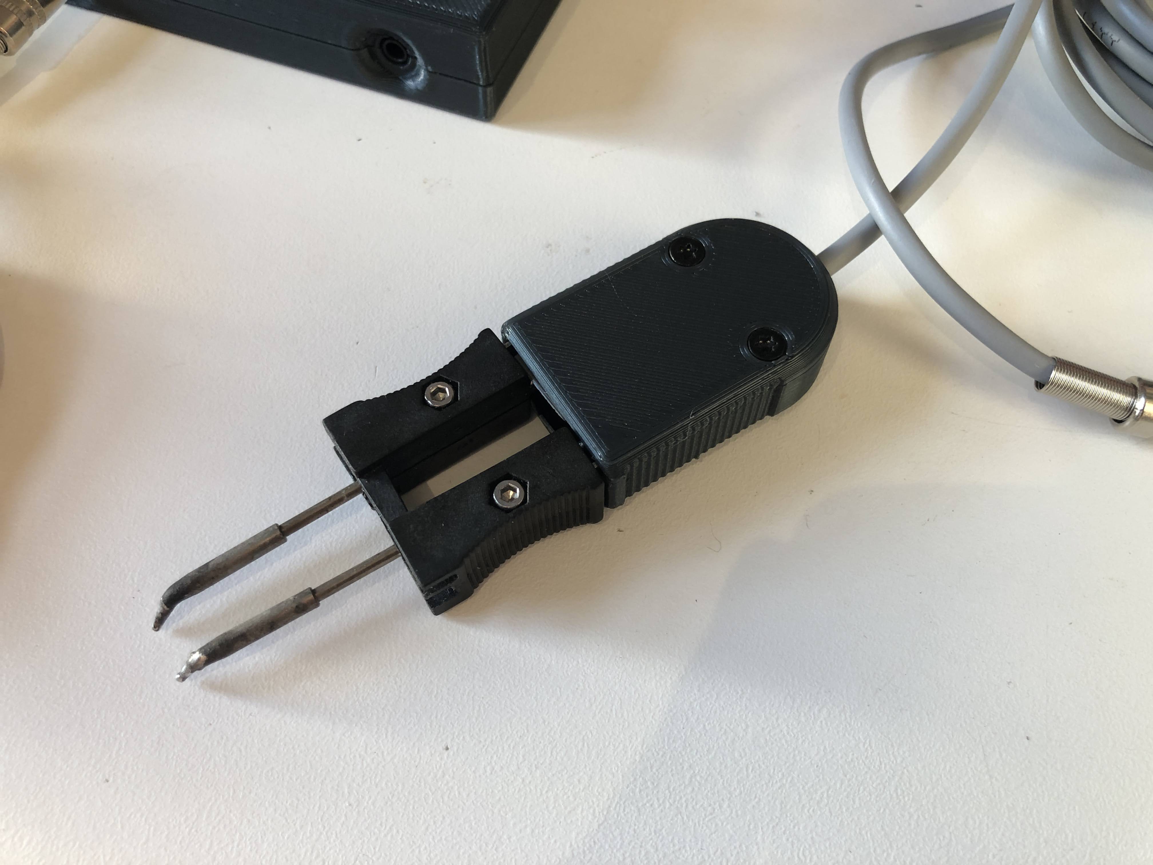
SMD Tweezers:
The major challenge in creating the SMD tweezers (really really amazing for SMDs) was to find the mating connector for the original Weller replacement.
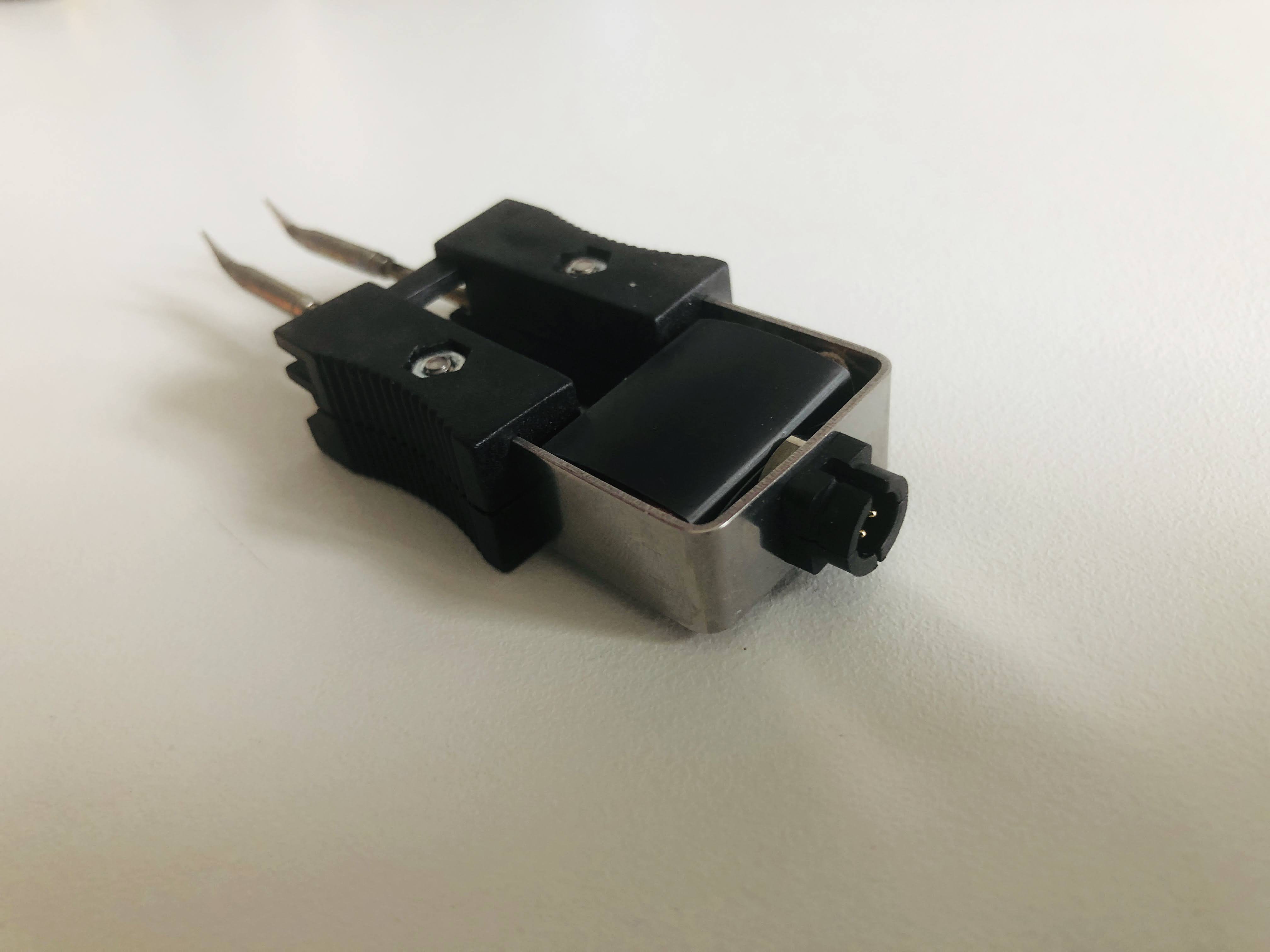
After finding the correct rare connector, it was rather easy to identify the resistive elements connections and TC connections.
The simple version of the SMD tweezers, uses a single channel of the soldering station (by drivign the resistive elements in parallel). In this way a single soldering station can handle a soldering iron and a set of SMD tweezers (in picture the simple ugly white case for the SMD tweezers V1).
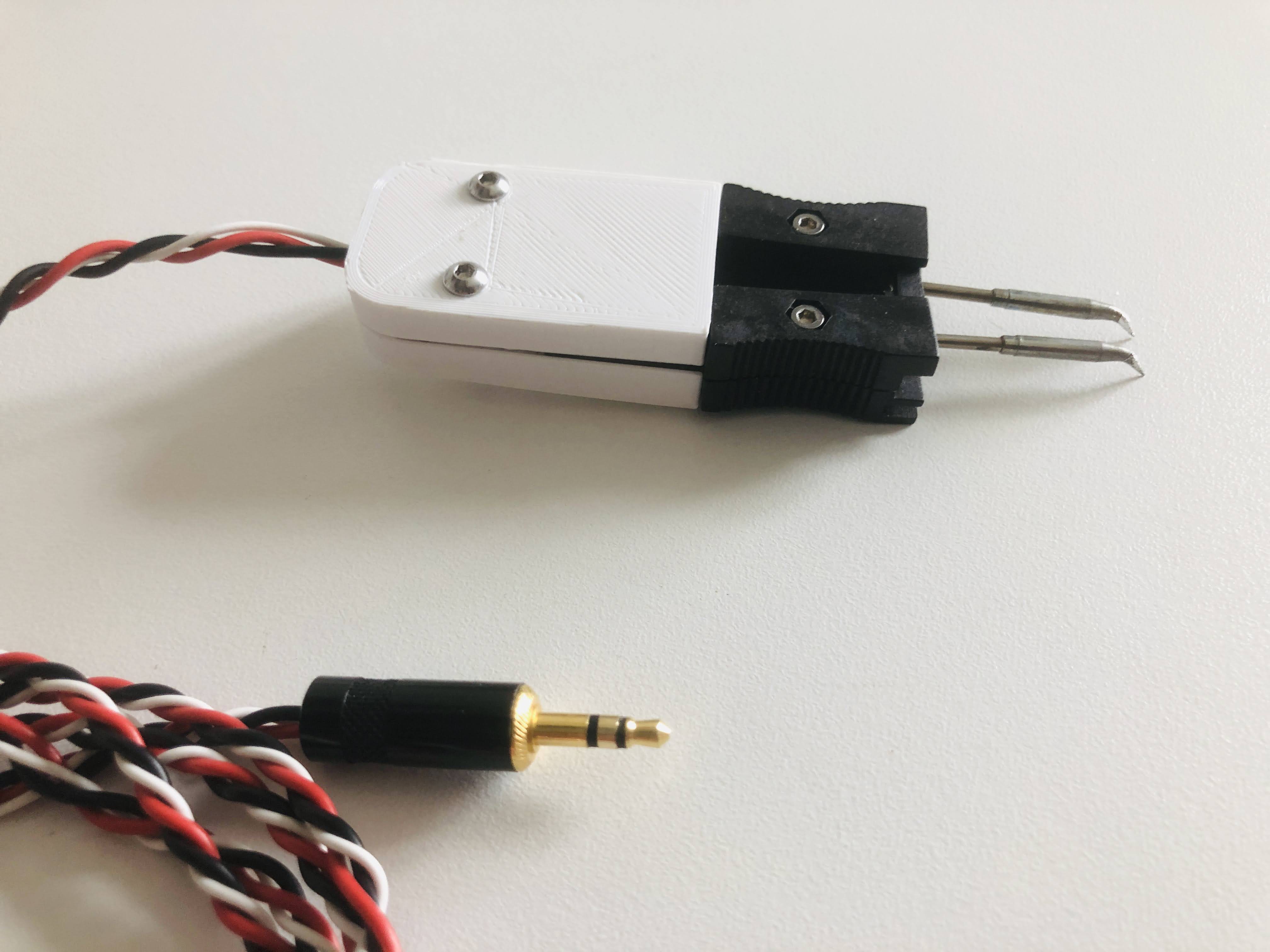
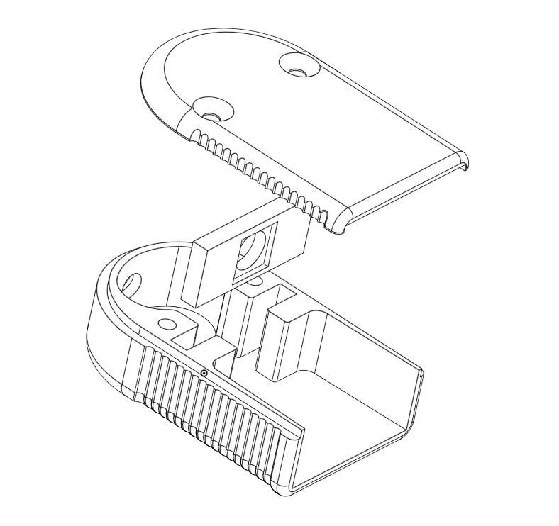
And some improvements to the tweezers holder. The design had to be based on three 3d printed parts
- two compose the outer case
- one parts allows mounting the receptacle connector and easy soldering of the wires
and finally the SMD tweezers optimized version with a nice complete view of the station :).
Future updates:
- Currently firmware version is 1.8b with multiple improvements is available from GitLab: https://gitlab.com/pittinihub/solderingrt1
- Future standby function (it will take a while... it is a bit complex/time demanding)
- Maybe include compatibility with C245 JBC iron-cartridges (secret work in progress...)


 Boz
Boz
 Joe Menard
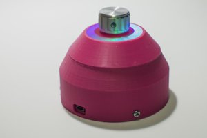
 Ákos Melczer
This setup destroyed several of my RTP and RTM tips when I used it with a 20V supply. The RTM tips lasted a few hours, but the RTP tip self-destructed almost immediately. Be careful, and either tweak the firmware, or use a 12V supply.