 Enrico Miglino
The Flying Platform
Hardware
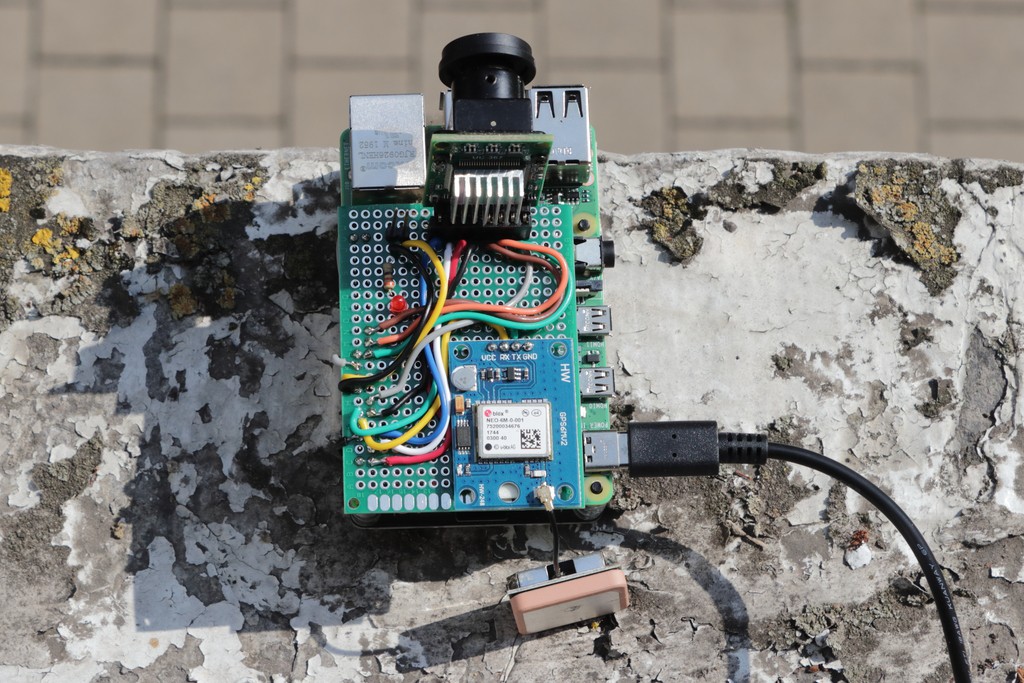
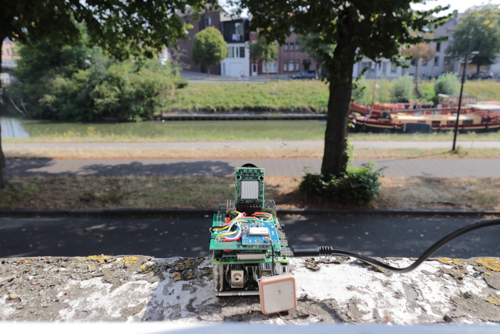
The first part of the project consists of the creation of a simple Raspberry Pi shield supporting the camera and the GPS on a single board plugged into the Raspberry Pi GPIO 40 pins connector.
Adopting this solution makes the whole device as much compact as possible for stability when fixed on the drone, as well as reducing as much as possible the weight due to the relatively limited payload of the drone (between 900 grams max).
These devices consume, respectively, the Raspberry Pi serial interface /dev/ttyS0 (the GPS module) and the I2C(1) and SPI(0) ports to interface the camera. To make the camera working efficiently I have developed a camera driver class derived by the original Arducam for Arduino (originally developed in C with a lot of issues and redundant, time-consuming functions) where the most important changes are the conversion to a general-purpose (for the Pi only) C++ class, together with consistent improvements and revisions.
Note: all the software updates, as well as the related materials like the STL files and designs are constantly updated on the Nanodrone repository.
Camera: Usage and Performances
For testing the software along the development process, as well as verifying that the hardware complains to the expectations, I have developed a terminal, interactive testlens application to test the features and performances of the hardware and the processing algorithms. To verify precisely the performances a GPIO pin has been used as test-point; the below snippet shows the function called before and after the process under testing for time-compliance.
void debugOsc(bool state) {
    digitalWrite(DEBUG_PIN, state);
}
The DEBUG_PIN status (set to true when the desired process starts and false when the process ends) timing is checked with an oscilloscope to verify the precise time duration of the process.
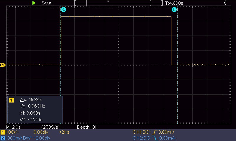
The above image, for example, shows the duration of the camera initialisation; due to the long time required to initialise the device it is done once before the acquisition sequence and the camera remains open for images capture until the acquisition session is not ended.
The timing performances with the Arducam controlled by a Raspberry Pi 4 is the following (using the ArduCAM class developed for this project):
- Camera initialisation: about 15.5 sec
- Image acquisition: from 20 ms (320x240) up to 1.5 sec (full resolution, 5 Mp)
The acquired image is never send outside of the Raspberry Pi (the flying module) but it is processed with a series of proprietary algorithms using the features of the OpenCV library to convert the images in multi dimensional arrays. The screenshot below for example shows the duration of 505 ms for the image equalisation and optimisation algorithm called automatically after every capture.
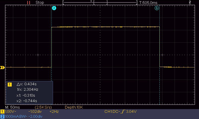
As the whole system should work real-time it is strategical the speed at which the captured images can be processed to extract the key information collected by the ground station. The image processing is applied to the captured images by specific APIs I am developing in the ImageProcessor class. Based on the tests done with the different capture resolutions the optimal image size for processing in a reasonable time (about 1 sec.) is 1600x1200.
Camera: the Lenses
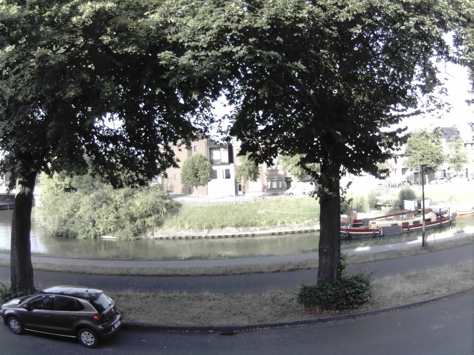
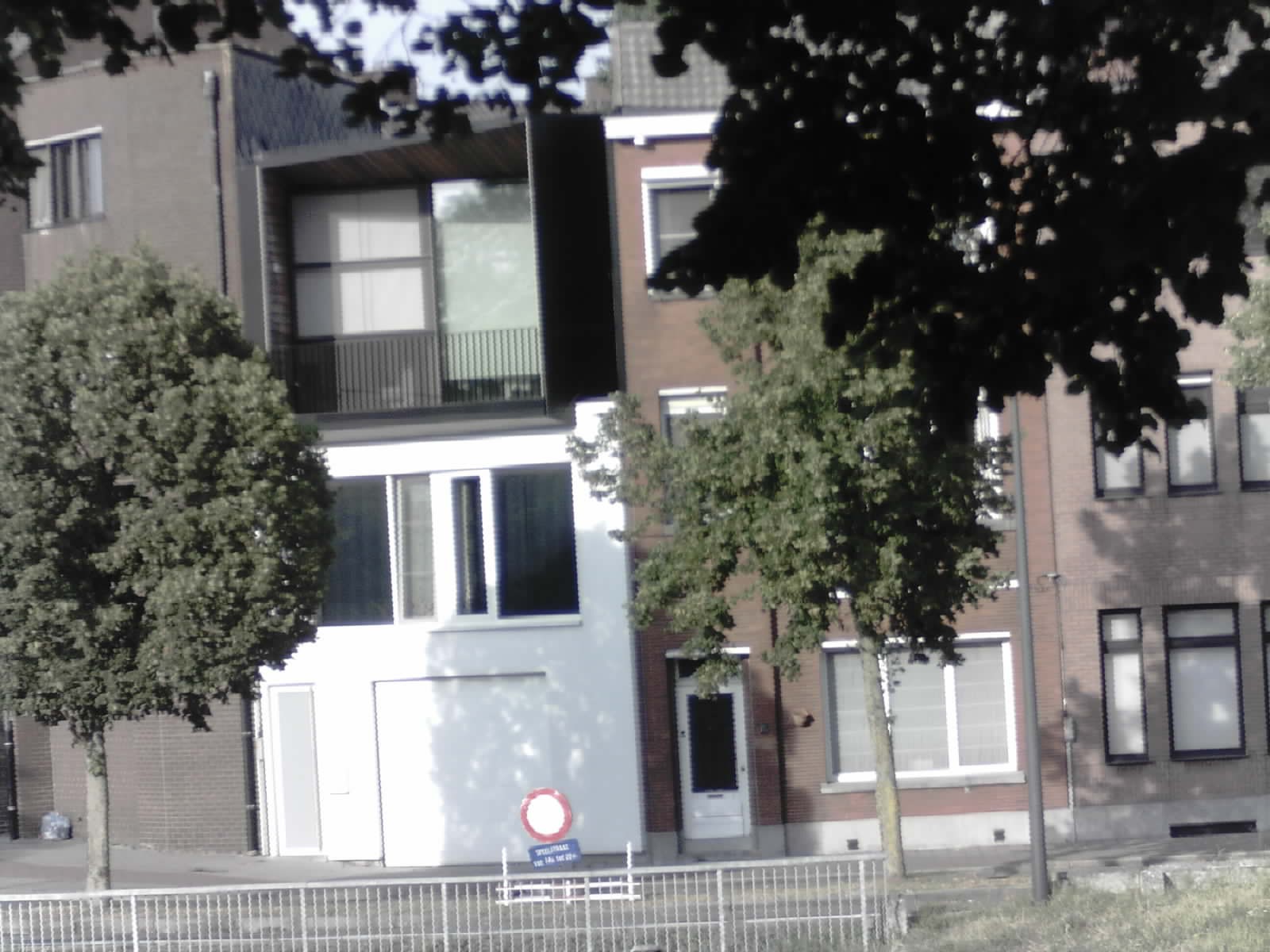
To be able to work in different visual scenarios, for example large fields, cultivation plants, small areas of terrain, ecc. I have acquired a series of different lenses for the camera and made some acquisition tests.
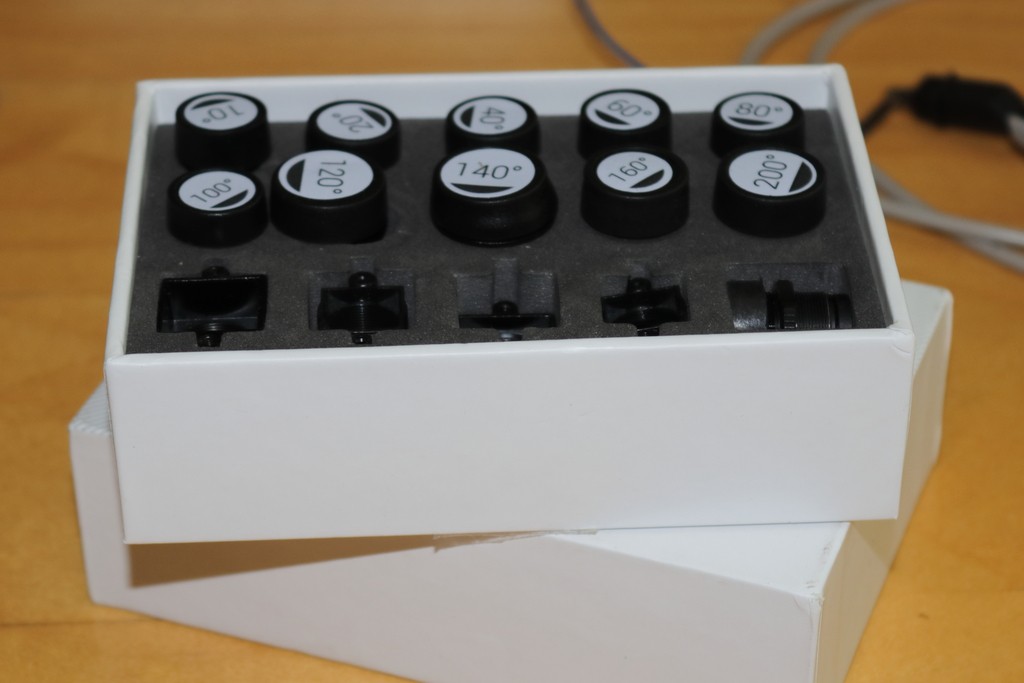
Above: the 10 lens set from an aperture of 10 Deg (telephoto) up to 200 Deg (ultra-wide angle)
Above: Indeed, the lens test images have been all acquired from the same point of view to have a comparison reference.
The images below shows some examples of different kind of lenses capturing the same scenario

Discussions
Become a Hackaday.io Member
Create an account to leave a comment. Already have an account? Log In.