 Silícios Lab
In this project, you'll learn how to construct your own PCB Car Arduino Module to learn about the control of robots.
Through this module, you'll learn how to power on motors to control wheel of the robots, light, and control of robot navigation direction.
For this project, you'll need of this following components presented below.
Supplies
The Arduino Car Module Project
One of the biggest difficulties in robotics is learning to control a robot. Thus, one of the first robots that are used is the two-wheeled robot.
These robots use two engines to control the direction of robot navigation through the environment.
In this beginning, many users have great difficulty in controlling the motors, because the circuit, at the beginning of learning, is complex.
Therefore, one way is to use the Robot Car Arduino module. In Figure 1, we are presenting the Robot Car Arduino Module.
As is possible to see in the project, the user can control several parts of the car. The user can control LED's to signalize the direction of the car with LEDs in the rearview.
In addition, the user can use rearview LED's to illuminate the via and power on LEDs for the Car Headlight. Finally, there is one led in each wheel.
Through the leads, the user can control the direction of the vehicle, in other words, the user can power on the motor for the car to straight ahead, go to left, go to the right or go to the back.

Figure 1 - PCB of the Robot Car Module for Arduino.
As is possible to see in the project, the user can control several parts of the car. The user can control LED's to signalize the direction of the car with LEDs in the rearview.
In addition, the user can use rearview LED's to illuminate the via and power on LEDs for the Car Headlight.
Finally, there is one led in each wheel. Through the leads, the user can control the direction of the vehicle, in other words, the user can power on the motor for the car to straight ahead, go to left, go to the right or go to the back.
Now, for you to understand the connections of the PCB, you can see the Electronic Schematic of the PCB is presented in Figure 2.
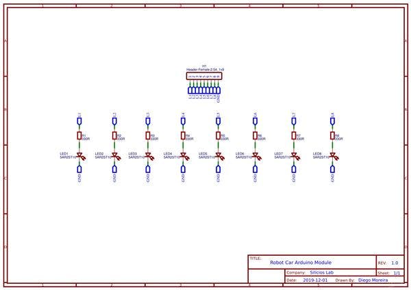
Figure 2 - Electronic Schematic of the Robot Car Module for Arduino.
As is possible see, there are 8 LEDs and a GND pin to connect and power on each LED in your Arduino Robot Car Module.
Therefore, to help you to create a good project, you can download the code and control your own car through Arduino.
        void setup() {  // put your setup code here, to run once:  //Config the pin 2 until pin 9 as OUTPUT  for(byte pin = 2; pin < 10; pin++)  {    pinMode(pin, OUTPUT);  }
}


void loop() {  // put your main code here, to run repeatedly:  digitalWrite(2, HIGH); //Signal light ON left  delay(1000);  digitalWrite(2, LOW); //Signal light OFF left  digitalWrite(3, HIGH); //Signal light ON right  delay(1000);  digitalWrite(2, LOW); //Signal light OFF right

  digitalWrite(4, HIGH); //Turn ON Left Headlight LED   digitalWrite(5, HIGH); //Turn ON Right Headlight LED

  digitalWrite(6, HIGH); //Turn ON Left Brake LED  digitalWrite(7, HIGH); //Turn ON Right Brake LED

  digitalWrite(8, HIGH); //TURN ON Left Wheel Motor  digitalWrite(9, HIGH); //Turn ON Right Wheel Motor

  delay(1500);

  digitalWrite(4, LOW); //Turn OFF Left Headlight LED   digitalWrite(5, LOW); //Turn OFF Right Headlight LED

  digitalWrite(6, LOW); //Turn OFF Left Brake LED  digitalWrite(7, LOW); //Turn OFF Right Brake LED

  digitalWrite(8, LOW); //Turn OFF Left Wheel Motor  digitalWrite(9, LOW); //Turn OFF Right Wheel Motor  }
Conclusion
Thus, through this PCB Arduino Module you can use to teach robotic through a simple module and easier the student to learn principles of programming and robot control.
So, if you have interesting, you can access the files on PCBWay.com website.
Acknowledgment
Thanks to the PCBWay for support the our YouTube Channel and produce and assembly PCBs with better quality.
The Silícios Lab thanks UTSOURCE to offer the electronic components.