OLED LED controller
Video: The Tenergy desk lamp modification (mostly talk about the user interface)
There are many 12V, white LED modules, used for lighting around the house. The modules light table tops/workbenches in the office room, the garage and the basement. All of the modules use a mechanical power switch. However! A smarter, general purpose switch with features was needed.
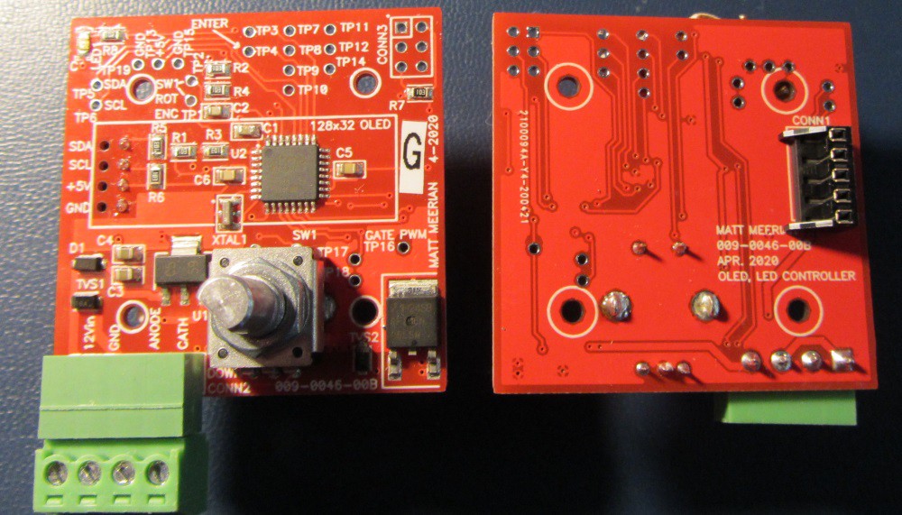
Figure 1: A populated “OLED white LED controller” PCB (top side and bottom side)

Figure 2: The display, enclosure, and knob added to the PCB
Goals
The main goals were:
-to allow the user to control the behavior of the LED's easily
-Set the behavior of the LED's at power up.
-control the dim level
-to turn off the LED's after a set amount of time
The hardware
For the MCU, a linear 5V regulator was used to step the 12VDC down to 5VDC. (Rev A of the board used a switching regulator, But, since the current was low, the less expensive/complicated linear regulator was used on Rev B) The MCU is an ATMEGA328PB, from Microchip. The controller uses a 128x32 pixel OLED display. (To initialize correctly, some of the displays require a wait time after power up, up to 2 seconds! Grr.) The header pins for the OLED go through the board to connect on the bottom side to a connector. The connector did not have a four pin version. So, a 5 pin version had one of the pins cut off.
The enclosure
Simple enclosures are good. An off-the-shelf enclosure base was used. The top part is a clear piece of 0.032” (0.81mm) thick poly carbonate with several holes for screws and one larger hole for the rotary encoder.
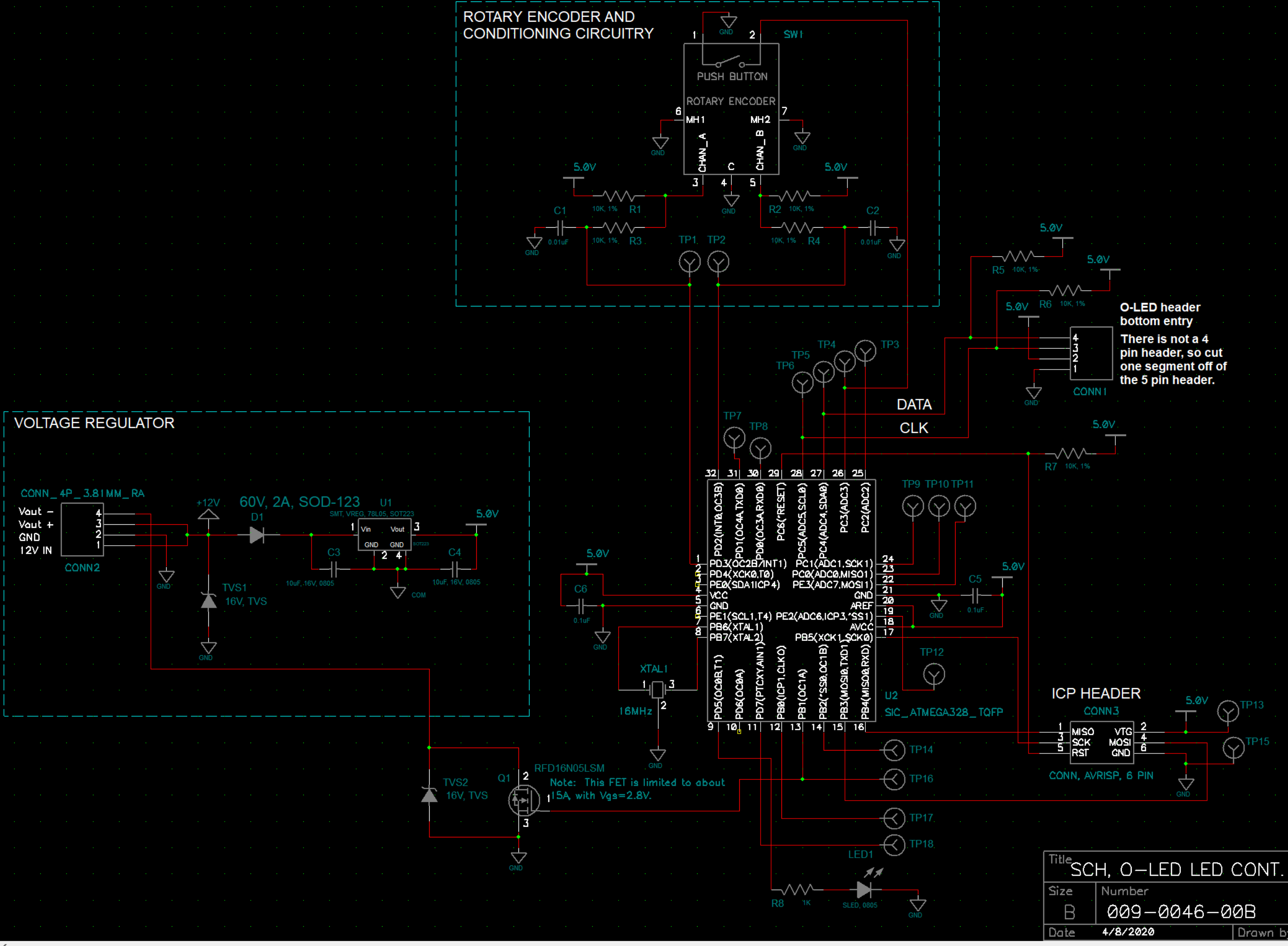
Figure 3: The rev B schematic
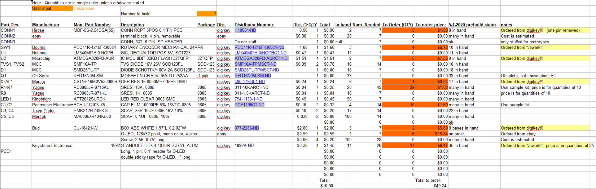
Figure 4: The BOM for rev B of the board

Figure 5: The Rev B PCB layout
The software
The Arduino IDE was used to develop software for the board. The main reason for using the Arduino code is the easy access to libraries, for the OLED and the rotary encoder. A MK-II programmer was used to program the ATMEGA328PB. The 'PB version of the ATMEGA328 has a few more timers and other features. Since the ATMEGA328PB only has 2K of ram, it is easy to run out when using the U8G2 graphics library. RAM usage is at 1.33K bytes for the latest revision of software.
The code is attached below.
(please note I don't write the best code in the world)
The Tenergy desk lamp modification
Tenergy desk lamps have a
capacitive touch interface. This allows the intensity and color
temperature to be controlled. But, there is one feature they are
missing: If you cut power to lamp, they always come up in the off
state. (there is not any EEPROM storage of variables) This does not
work well for the work benches, since power is applied to the bench
through a mains power switches.
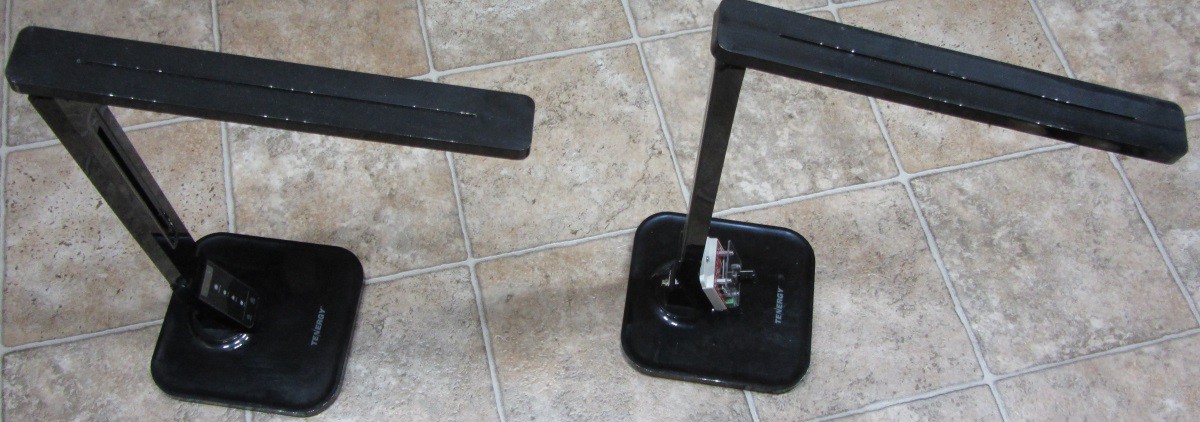
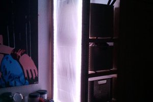
Figure 6: The unmodified Tenergy lamp is on the left, the lamp with the new controller is on the right
The Tenergy lamp operates off of a 12V wall pack. The lamp contains roughly 6500K and 3200K LED's, on separate channels. These LED's are turned on at various levels to set the intensity and color temperature. Color temperature is not really an important factor, so the LED's were wired together for the new controller.
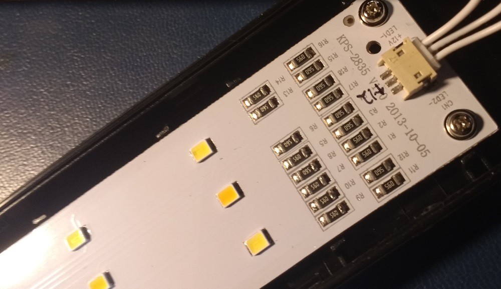
Figure 7: The LED's in the top side of the lamp. (The “warm” LED's are in the center line and the “cooler” LED's are along the edge)
The two existing controller circuit boards were removed from the lamp. The four pin, 1mm connector that goes to the LED board was salvaged from the existing circuit boards, to be used with the new controller. A new 2.5mm barrel connector was added in the back of the lamp for power.
Summary
So far, the controller is doing well. The operation has been stable and configuration features seem to be doing their job. There have been several tweaks to the software, but that is understandable.

 matt thurstan
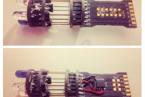
 davedarko
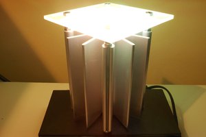
 Enrico
 icstation
Great Work,
i was looking for a 128X32 OLED rotatory encoder menu, but i was wondering if your code (the section related to OLED menu scrolling) may work for an Arduino Micro Pro. I will make 3x4 macro keyboard with it, and i want to include a OLED display and a Encoder in oder to modify the keayboard function/mode and display it.