 Tim Ryan
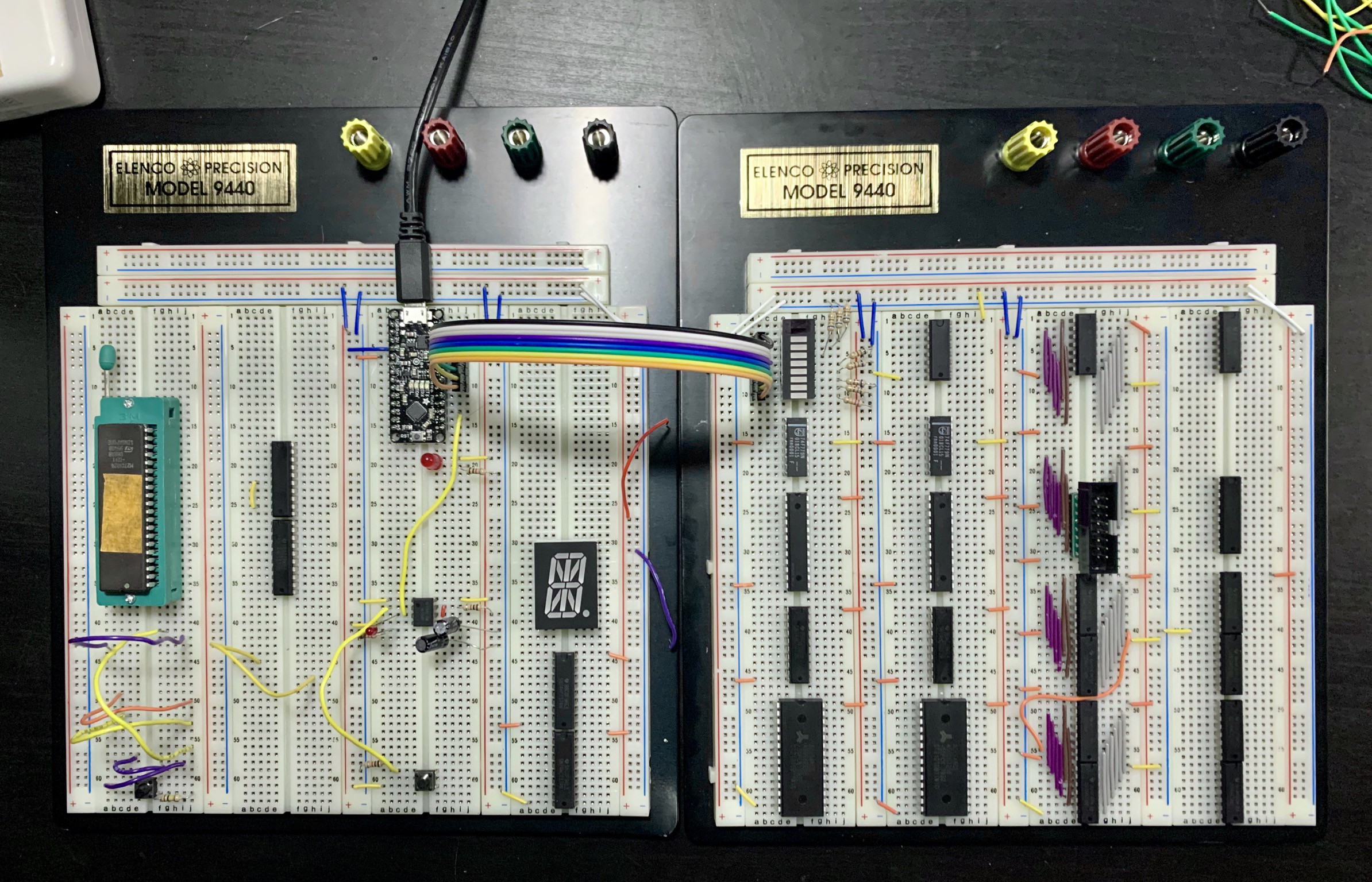
When I started this project I wasn’t sure if I were going to attempt to breadboard this design, but now I’m grateful I tried. It looks like this will span several breadboards so I’ve connected two sets of four together, which should be enough? As a way of debugging the circuit immediately without fussing with EPROM programming and counter logic, I am using an Arduino-like from Adafruit to drive the ROM bus and perform branches. I also put together a step circuit using a 555 where each clock cycle can be controlled by a button press.
The biggest challenge seems to be how to wire up a 16-bit bus, which consumes a lot of wires and makes wiring really tedious. I’m trying to split all logic into 8-bit slices, so the high and low bytes of the CPU bus can be handled separately. On the right module, beardboards 1 and 3 correspond to the high byte, while 2 and 4 control the low byte. The 16-pin IDC interface is the TOS bus, which loops back to the input of the Top it Stack register on the left module. Hopefully this breakdown makes it easy to keep wires under control when I start putting together the bus.
My biggest blocker: I didn’t learn about the distinction between the 373 (silly pin order) and 573 (left to right pin order) before trying to use these chips. Now I’m stuck waiting for them to come in, since the alternative is cutting a lot more custom wire lengths!
Discussions
Become a Hackaday.io Member
Create an account to leave a comment. Already have an account? Log In.