Video demonstration
- I demonstrate and also explain how it works in this video.
Block diagram of the project
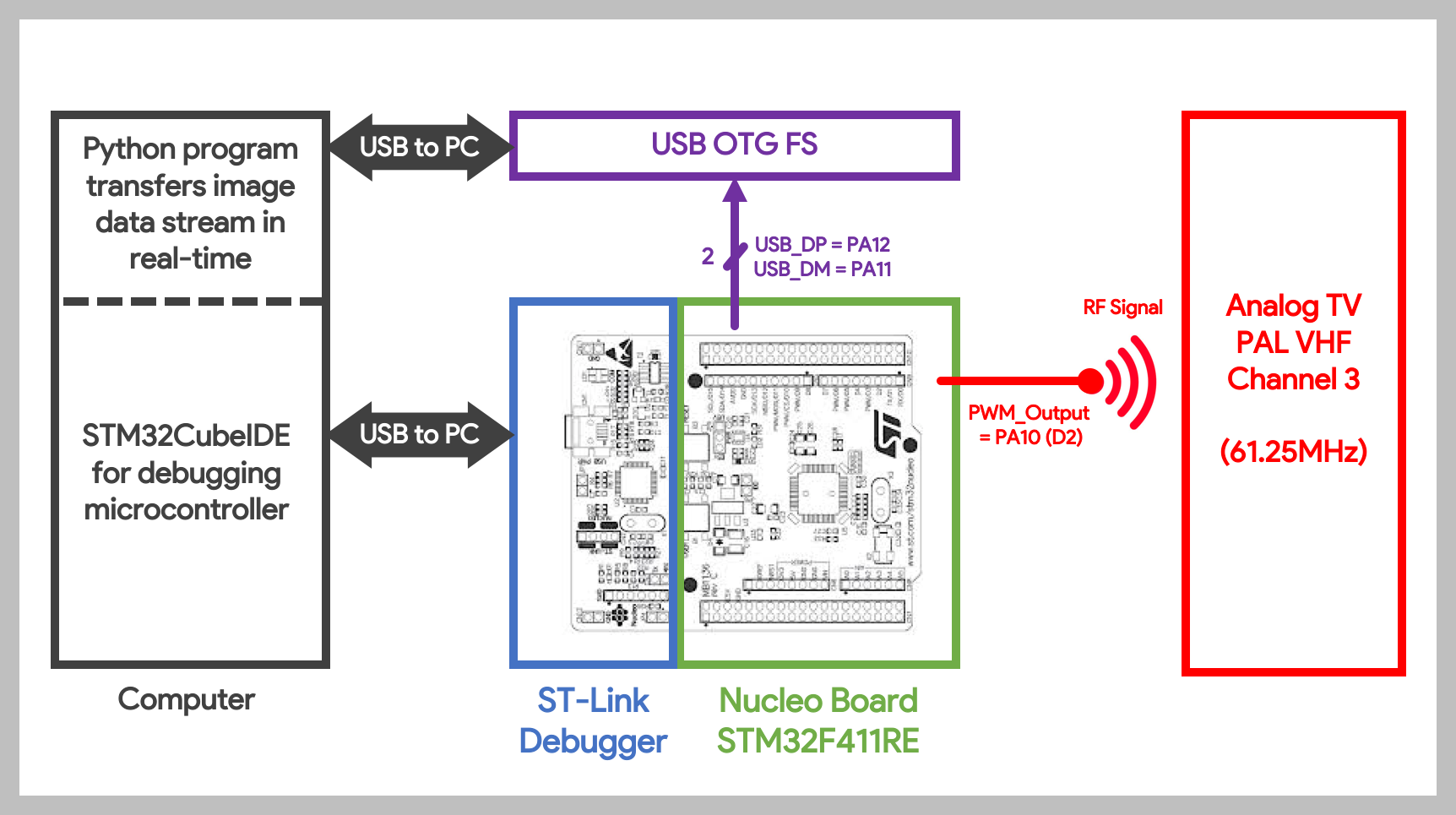
- To wire this project up, only 3 GPIOs are needed.
- PA10 = PWM output serving as the antenna
- PA11 = USB D- pin
- PA12 = USB D+ pin
- This diagram shows the schematic of the project
Inspiration of the project
- My initial idea was to display images on it. I wanted to make a simple & cheap analog TV transmitter from parts I had lying around.
- I searched online and I came across @CNLohr avr_vhf project. He used an AVR ATTiny85 to generate PWM waveforms which were picked up by his TV.
- I found it clever and genius because I didn't know that a square wave PWM could serve as AM modulation.
- In his case, he both overclocked the MCU to 30MHz and used PLLx8 to the timer. Thus, his timer is clocked at 240MHz and with a period of 4, its output is 60MHz (approximately the frequency of CH3).
Technical explanation
- I looked around for an alternative because I did not have a fast enough microcontroller. (ie. to transmit at CH3 of 61.25MHz, I need the timer to be clocked at minimum 2x the speed -- at least 122MHz for PWM)
- I am not a fan of overclocking the internal oscillator because the frequency drifts easily.
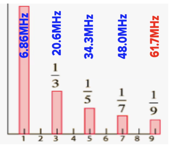
- I realised that PWM is a square wave and thus it has odd harmonics. I thought it would be creative if I could simply output a lower frequency (of which its harmonics matches the TV channel frequency).
- In my case, through trial and error, I managed to get a clear image on the TV with a 6.86MHz PWM output. The 9th harmonic is 61.71MHz which is about CH3 frequency.
- In theory, you can replicate this behaviour on any slow microcontroller (like an Arduino Uno which does not have PLL). Because you can take advantage of the odd harmonics to achieve the channel frequency.
Real-time video streamer
- Next, I wrote a Python script to transfer image data from a PC to the microcontroller.
- Without external components, I tried USART and it is possible, which means but the maximum baud-rate of 3 million gave me about 10 FPS.
- The fastest way was to use DMA and USB OTG FS (Full-Speed). I simply needed to add a USB cable and 2 wires (D+/D-).
- The MCU receives the video stream from the PC and transmits it to the TV using AM modulation via PWM. It is fast enough to transfer GIF files in real-time.
Where I sourced these components
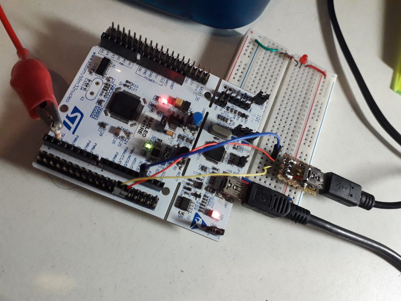
| Portable Analog PAL TV | Found at home in my store room |
| STM32 NUCLEO-F411RE | Cheap microcontroller I had around |
| Mini USB Port | Leftover from my other projects. I didn’t have a breakout board so I hand-soldered wires onto a perfboard |
Why I used these components
- Right now, due to the global pandemic situation and stay-home measures in place, I have more free time. However, I am constrained of resources as shipping delays have made it difficult for me to source components. My goal was to use whatever I had lying around, with as few external components as possible.
Future improvements
- Right now the Python program running on my PC supports only images and GIF files which are transferred in real-time to the microcontroller. I am planning to improve on it, perhaps by using an ffmpeg stream instead. I am still learning how to use ffmpeg and, hopefully, it can stream actual videos or even a webcam stream.
- A square wave is usually not the way people transmit because the harmonics can actually cause interference to other channels. I am now experimenting with adding a bandpass filter to the output, so that I can have the best of both worlds
- (1) transmitting at a slower frequency, and
- (2) a clean sine-wave AM modulated frequency
- For the issue on the distorted effect on the TV, in theory it can be fixed by synchronising the TV refresh rate to the PC python program. I'm still wondering how to exactly fix it because the USB transfer rate varies slightly each time it is done.
Conclusion
I hope this project inspires you to do something better.
Feel free to ask any questions or suggest improvements. If you spot any...
Read more » zst123
 Gorky
Gorky
 George Gardner
 Daphne
 Louis H