IoT based Smart Switchboard

GOOGLE Assistant
To
Control your Lights & Fan
Home automation has become very common now days and people are using IoT to automate everything in their home. Today, I am going to explain you how we can create a cheap google assistant based smart home appliance control system which you can also sell as product.
After going through this project details you will be able to build a smart, low cost, wifi enabled devices that lets you control home lighting,electronic devices in your home from your android phone anywhere, anytime and also you can check the status of your lights, Fan, TV, etc. Yes, your existing switchboard can get smarter with just a small change and NOT much cost.
Hardware Components:
- Arduino UNO
- ESP8266 WiFi module (ESP-01) /NodeMCU
- Relay Module 5 volt
- Wires for connection
- AC to DC 5 volt power supply
- LM1117 or AMS1117 3.3V regulator
- AC appliances
- WiFi router
Tools
- Soldering iron
- Wire cutter
- Screw driver
- Multimeter
- Electrical tape
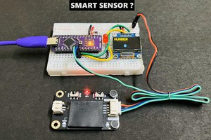
Connect ESP8266 with Arduino for Programming
 |
| Programming ESP-01 |
Pin Description
- VCC: Power supply pin of ESP-01 which can be supplied with 3.3V DC
- GND: Ground reference pin of ESP-01
- TXD: Used as UART Transmitter pin or GPIO 1
- RXD: Used as UART Receiver Pin or GPIO 3
- RESET: It is used to reset the Module and it is an active LOW pin.
- CH_PD: It is the chip enable pin which is an active HIGH pin.
- GPIO0: This pin serves two purposes. One is as General purpose Input/output and other is to enable Programming mode of ESP-01 when connected to ground
- GPIO2: This is a General purpose Input/output pin.
Connect the ESP8266 module with Arduino UNO as shown in the figure above, make sure that Rx is connected to Rx and Tx is connected with Tx as ESP-01 module is not 5 Volts tolerable use voltage divider for Rx. When you want to program the board check first if GPIO0 is connected to ground otherwise you will not be able to upload any code to your ESP-01
Enable pin should also be supplied with VCC and optional for RST.
Setup Arduino IDE
Install Blynk library for arduino IDE following this link here
After installing suitable library open new sketch and copy the code given below:
Edit SSID, PASSWORD, Authentication Key with yours before uploading to your ESP8266 module
Don't just copy paste, try to improve the code and the code is self explanatory if something not understood do let me know
Code:
#define BLYNK_PRINT Serial
#define RELAY_PIN_1 2
#define PUSH_BUTTON_1 1
#define VPIN_BUTTON_1 V2
#define RELAY_PIN_2 0
#define PUSH_BUTTON_2 3
#define VPIN_BUTTON_2 V0
#include <ESP8266WiFi.h>
#include <BlynkSimpleEsp8266.h>
char auth[] = "bccggllfyufjvbbm";
char ssid[] = "Free";
char pass[] = "12345678";
BlynkTimer timer;
void checkPhysicalButton();///
int relay1State = LOW;
int pushButton1State = HIGH;
int relay2State = LOW;
int pushButton2State = HIGH;
// Every time we connect to the cloud...
BLYNK_CONNECTED() {
// Request the latest state from the server
Blynk.syncVirtual(VPIN_BUTTON_1);
Blynk.syncVirtual(VPIN_BUTTON_2);
}
BLYNK_WRITE(VPIN_BUTTON_1) {
relay1State = param.asInt();
digitalWrite(RELAY_PIN_1, relay1State);
}
BLYNK_WRITE(VPIN_BUTTON_2) {
relay2State = param.asInt();
digitalWrite(RELAY_PIN_2, relay2State);
}
void checkPhysicalButton()
{
if (digitalRead(PUSH_BUTTON_1) == LOW) {
// pushButton1State is used to avoid sequential toggles
if (pushButton1State != LOW) {
// Toggle Relay state
relay1State = !relay1State;
digitalWrite(RELAY_PIN_1, relay1State);
// Update Button Widget
...

 Iulian
 ElectroBoy
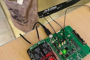
 Rob Lauer