 HummusPrince
Before doing anything fancy, I must build something that oscillates at some frequency that depends on the value of my passives. For resistance and capacitance, it seems as if using the RC characteristics of them in series would be the simplest way.
This means building some sort of an astable multivibrator. The famous 555 timer might do, but foreshadowing on my side (knowing my next steps considered as cheating?) got me using op amp circuits directly.
Explaining op amps is out of my scope here. If you don't know what they are, consider going through some tutorial - Google seem to give decent results for "op amp tutorial". Anyway, suffice is to say that opamp for analog are kinda what arduino is for embedded - By using them you can concentrate on the operation of your circuit, while skipping many horrible non-idealities that usual devices have (input/output impedances, gain levels, nonlinearities). You'll pay penalties in performance and other stuff for this.
For opamp I'm going to use some LM324 I desoldered from a dead UPS. This is quite a standard opamp for simple, low frequency applications. Each package has 4 identical opamps, and given that I don't expect anything above 100kHz, this seems to do the job.
You might wonder what that circuit does:
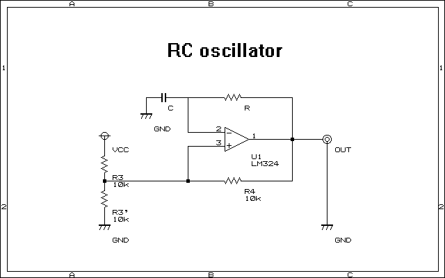
R3, R3' and R4 make an inverting Schmitt-trigger together. As I use a single supply, I want it to work around Vcc/2, which are generated by R3 and R3', which by Thevenin's theorem are equivalent to a Vcc/2 voltage source with resistance of R3||R3' = 5kOhm = 1/2*R4.
It means that the output will be Vcc until the negative terminal of the opamp is brought to 2/3*Vcc, at which the output would switch to 0 until the negative terminal is brought to 1/3*Vcc.
The upper branch with R and C is a typical RC series circuit. When the output is Vcc, the capacitor C gets charged through the resistor R, and when output is 0 it is decharged.
Due to the inverting nature of this certain Schmitt trigger, it means that it's going to oscillate. It can be shown that this circuit gives a square wave with duty cycle of 50% and frequency:
I built it and it worked quite flawlessly. The frequency was not accurate, and I suspected that it's because this opamp is not rail-to-rail, thus altering the 2ln(2) factor. Taking that into account gave very accurate results.
This circuit is very simple and well studied - tons of information can be found on the web. This will be the basic topology for my oscillators.
Theoretically, replacing the RC circuit with an LR one should do the exact same job, as the feedback coefficient of the negative terminal remains the same, but with L/R instead of RC this time:
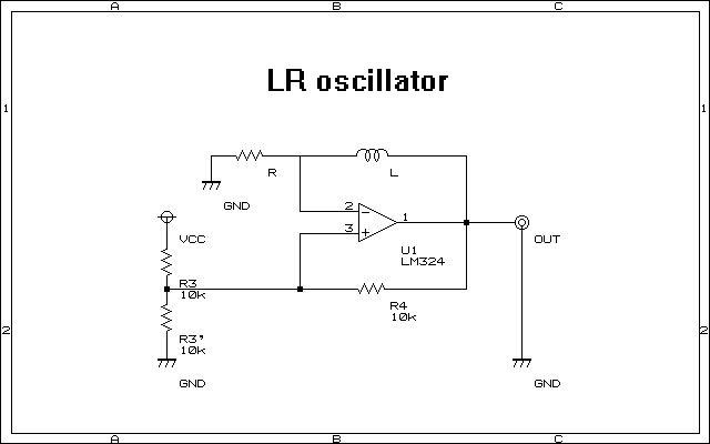
This should oscillate with
This is awesome - the frequency is proportional to the resistance!
However, there are problems.
The first problem I've encountered was practical: for a reasonable inductance, say 1mH, one needs to use very small R: for 10kHz, which is the largest that my counter can get without prescaling, one gets R~14Ohm. That's plain tiny - it's hard to find resistors in this range, but more important is that it'll take huge amounts of power, which the opamp won't ever be able to supply.
Prescaling by 100 requires 1.4kOhm, so you might thought that it would work. However, it pushes the opamp to it's limits, oscillating at 1MHz. Also, for smaller inductors this would still be a no-go.
To be able to study it properly, I need a big coil, preferably about 1H. Just like this guy:
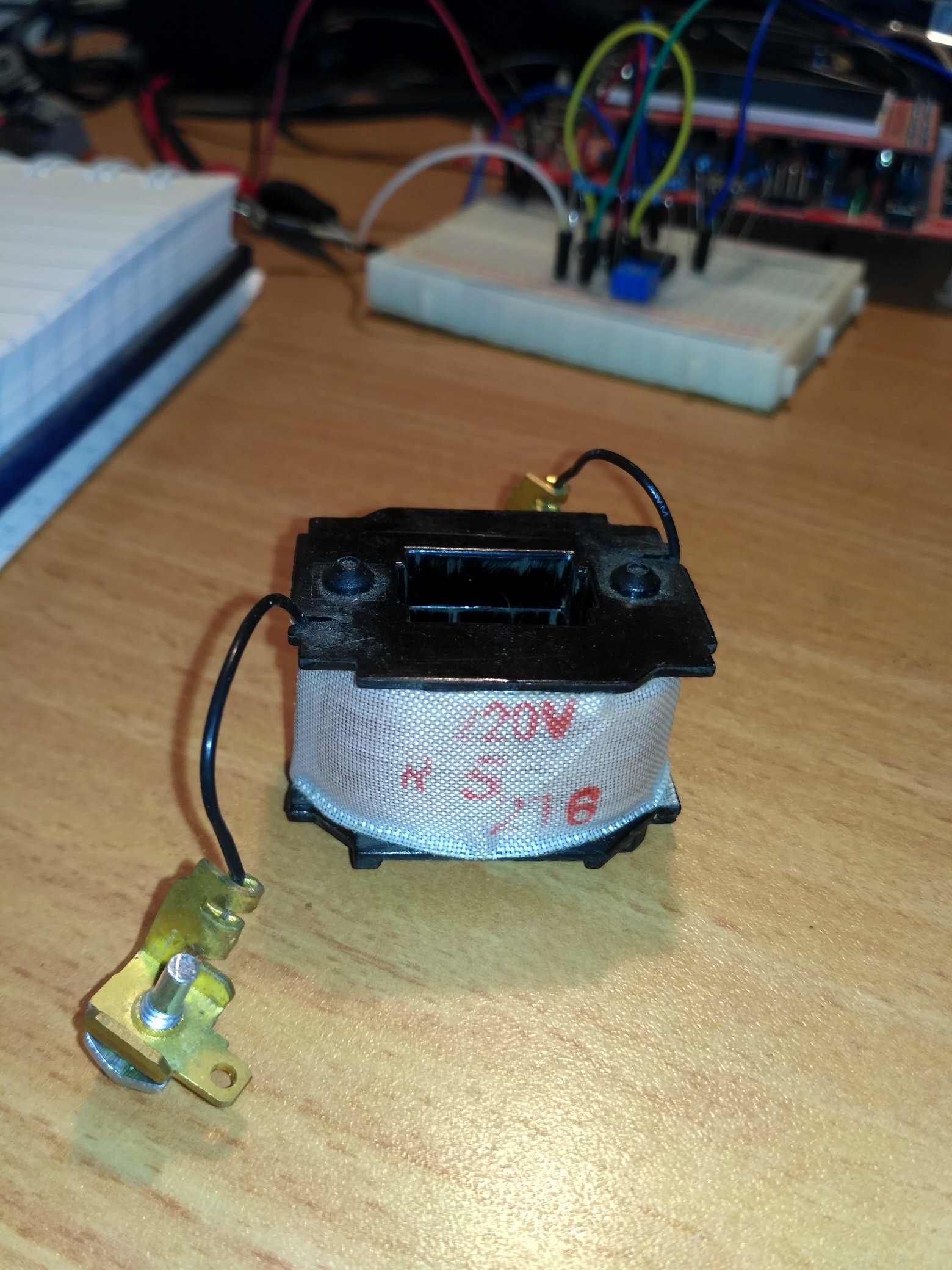
I think that it used to be a clutch coil of an A/C compressor. It's quite enormous, I think it gets to 1H.
The oscillator works with it quite well:
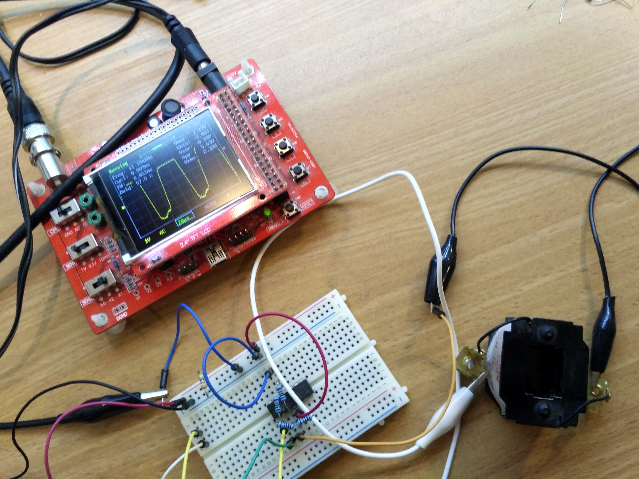
However there are some noticeable quirks:
First and foremost, the waveform look funky. It's not so square and has a noticable ramp. Also it has this extra bump while output is low. I suspect that the bump is a voltage spike on the inductor that is discharged through the LM324 protection diodes.
Another thing is the minimal frequency - below some resistance for R the circuit will not oscillate. While it can be attributed to the opamp unability to drive this load, I still saw that for a smaller inductor it was a lower value.
Turns out that I didn't take into account the internal resistance of the coil. This alters the oscillation frequency, and marks a minimal value for R:
Where R_L is the internal resistance of the inductor.
This makes sense - if it does not apply, the negative terminal never go past the positive one and the Shcmitt-trigger won't invert it's output. It's equivalent to saying that the negative feedback is larger than the positive feedback in this case, and the circuit is overall stable.
In this specific case, it means that R is at least half of R_L, which for my huge inductor is a whopping 475Ohms. However I saw that below R~1.2kOhm the opamp did not oscillate. Probably the load was too big for it.
Maybe the worst problem is that the circuit oscillates without R at all. It seems that it's own parasitic capacitance + the one on the breadboard are enough for it to start oscillating on it's own, at about 100kHz. I think that the huge ramp also has to do with the parasitic capacitance and resistance of the inductor.
This is the thing about real inductors - they're much less ideal than real capacitors. This is why people don't like them, along with their size, cost, their tendency to couple to each other, and many more peculiarities. While I might be able to measure inductance correctly by implementing some special workarounds, it's evident that it won't even do for resistance measurement.
No, it becomes crystal clear that I need to get farther into the analog realms to achieve my goal - and that would be by inverting impedances.
Discussions
Become a Hackaday.io Member
Create an account to leave a comment. Already have an account? Log In.