 HummusPrince
The frequency meter concept was proved, but there are some flaws. Most of these relate to the poor oscillator used for the time base. It's frequency fluctuate depending on supply voltage, temperature, residual capacitance from the environment (breadboard?), weak coupling to other signals nearby (mains 50Hz) and more.
Luckily, there's a solution for that. Quartz crystal resonators are free from most of these flaws, and I have lying here some 32.768kHz xtals. These are very accurate, and 32768 is 2^15, thus easily divided using the CD4060. They are also high impedance (10s of kOhms), and thus very power-efficient. This is also why they are super popular and used in virtually every watch and wall-mounted-clock.
CD4060's datasheet recommends using a crystal with a regular parallel resonant configuration:

My crystals were scavenged, probably detached from some dead product long time ago. As I don't the recommended values for the passives, I had to play with the values until I got it to work:
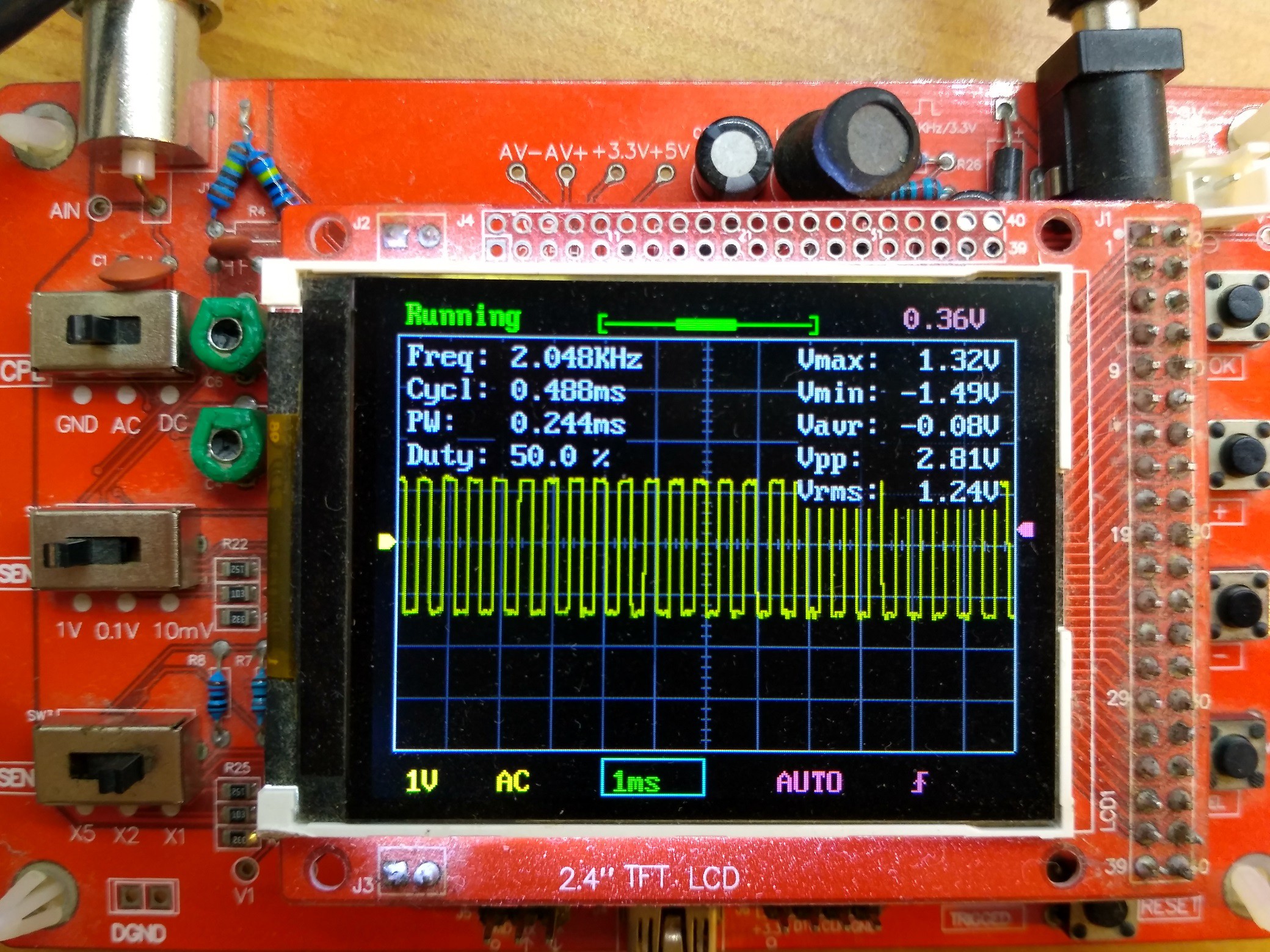
Measuring at Q4 of the CD4060 you get the clean 2048Hz expected. Good one.
Quadrupling the clock from 8192 to 32768 means that the lowest frequency I get from the CD4060 is 2Hz. Not good enough, as I need 1Hz. Thus I decided to use another CD4017 as another divider (I had no flipflops lying around).
Lets see if the modded circuit works:
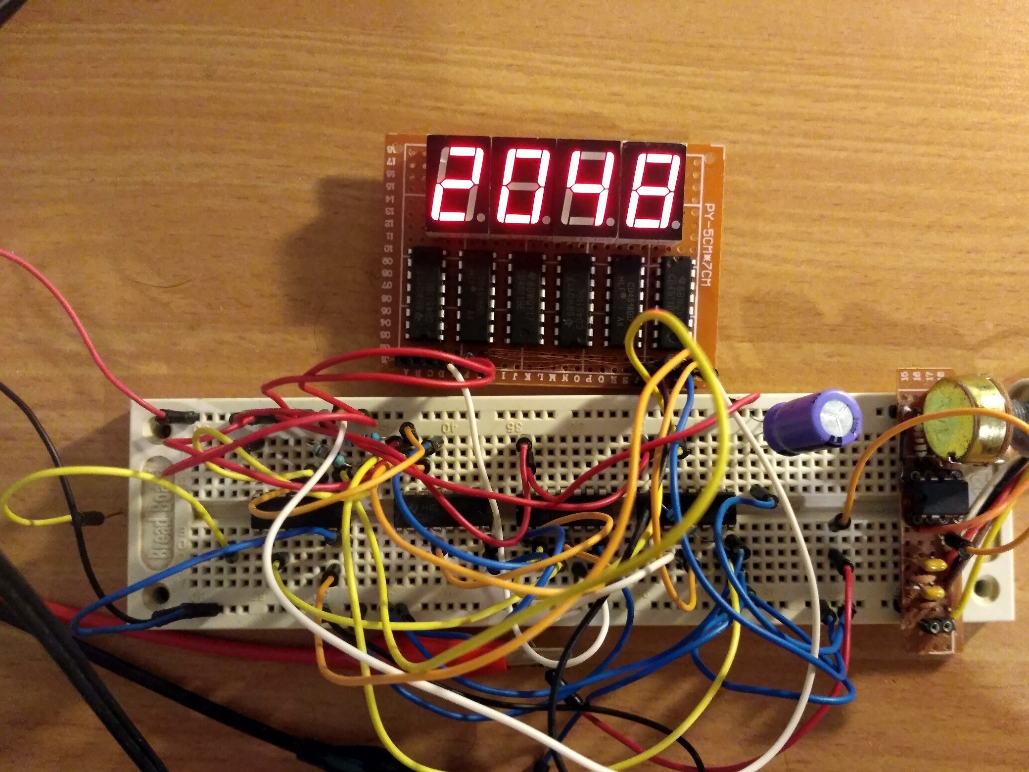
Measuring the frequency of Q4 in the CD4060 you see 2048 = 2^11 as expected.
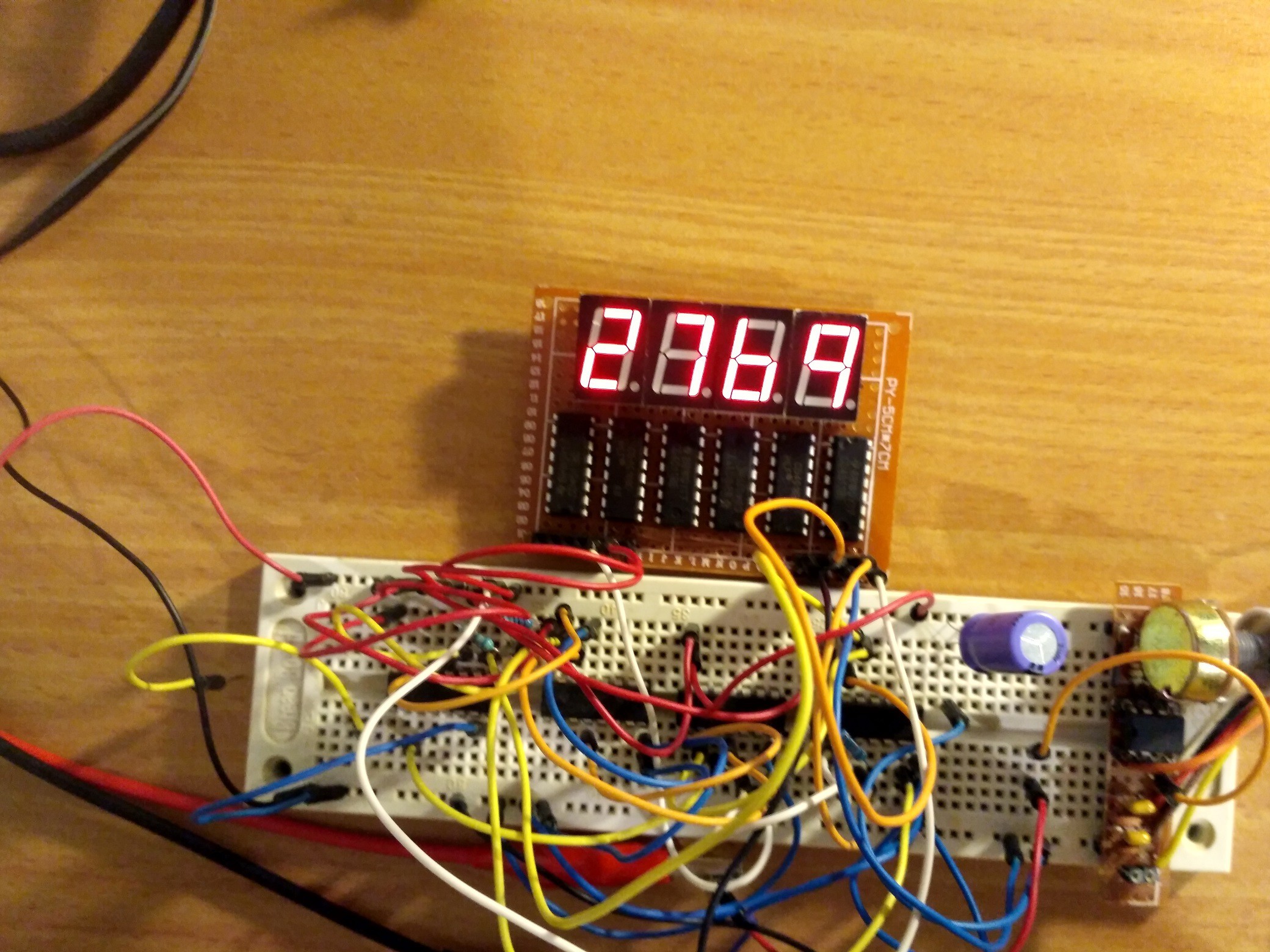
Measuring the clock itself. One will expect to see 32768 ticks - which are 1 second - plus an extra tick for the latch control signal to go high. When reaching 10,000 the counter should overflow and begin counting from 0 once again, and this should happen 3 times each second for that signal, and you'll be left with 2768 + 1. That's exactly what I get, so it must be good to go, logic wise.
Like last time, it still does no ensure accuracy. Lets compare it with my chinese pal:
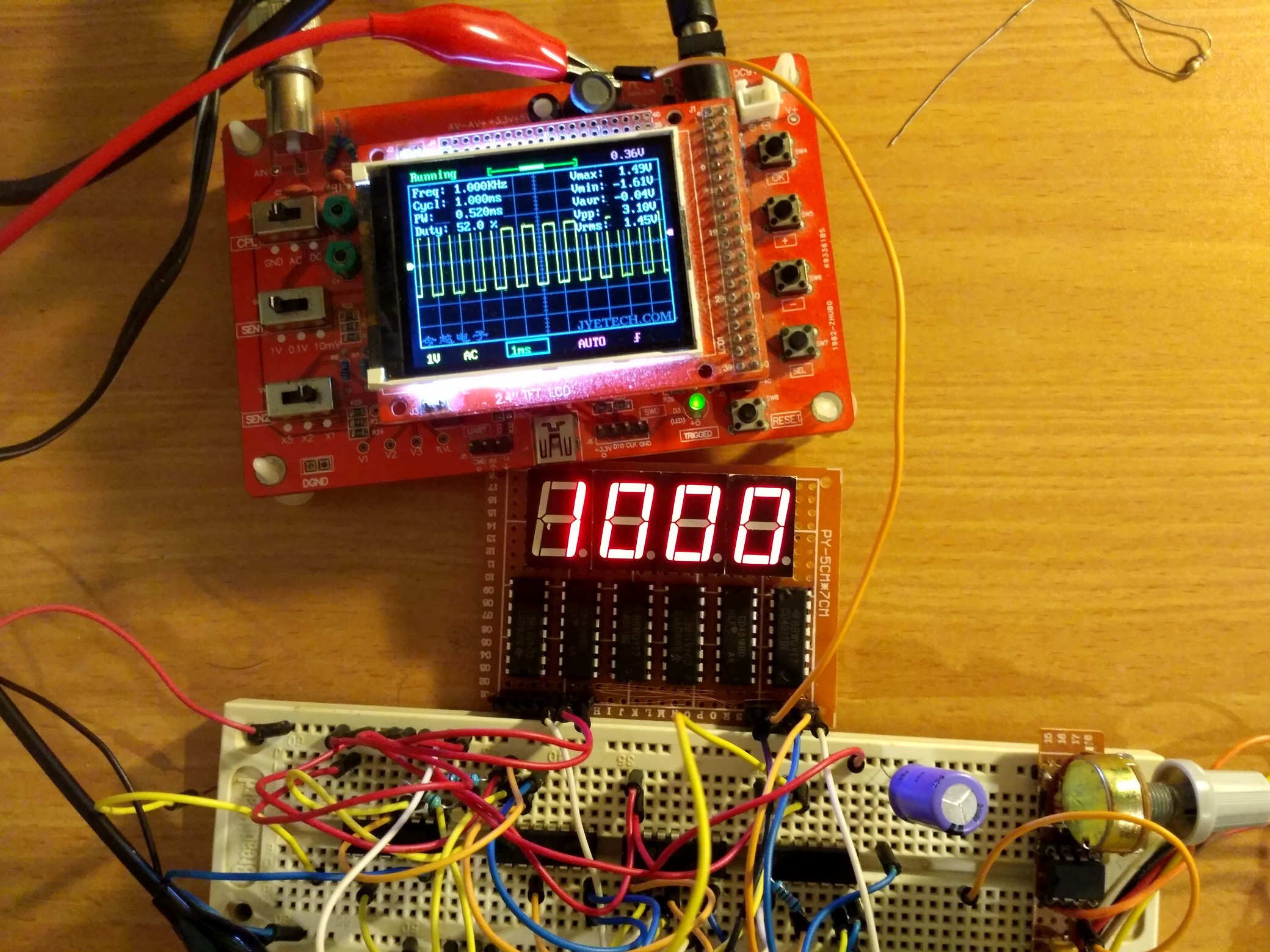
The 1kHz calibration signal of the toyscope looks very good on the counter.
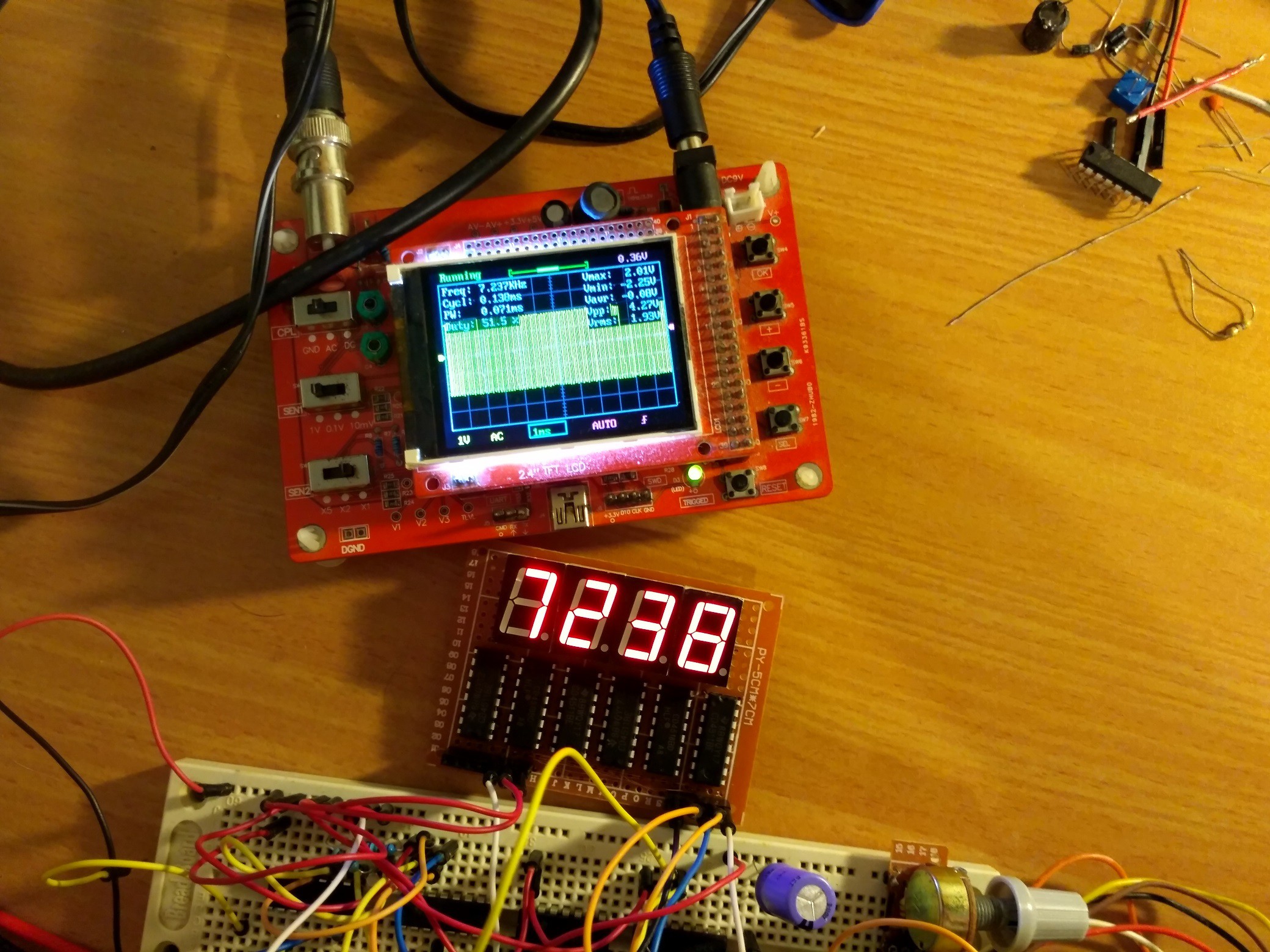
Here is a signal generated using a not-so-stable 555 astable timer (seen on the right side of the breadboard). The toyscope and the counter agree very well.
I decided to add a X10 and X100 prescaler. Using another CD4518 to divide the input signal by both ratios seemed only logical.
This is the resulting circuit:
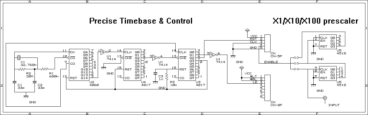
On the breadboard I've omitted the capacitors altogether, but when I'll put it all on a protoboard I'll probably add these. The oscillator probably is working good due to high parasitic capacitance in the breadboard, and when assembling I might choose for the caps different value than what's on the schematic.
The prescaler works well too:
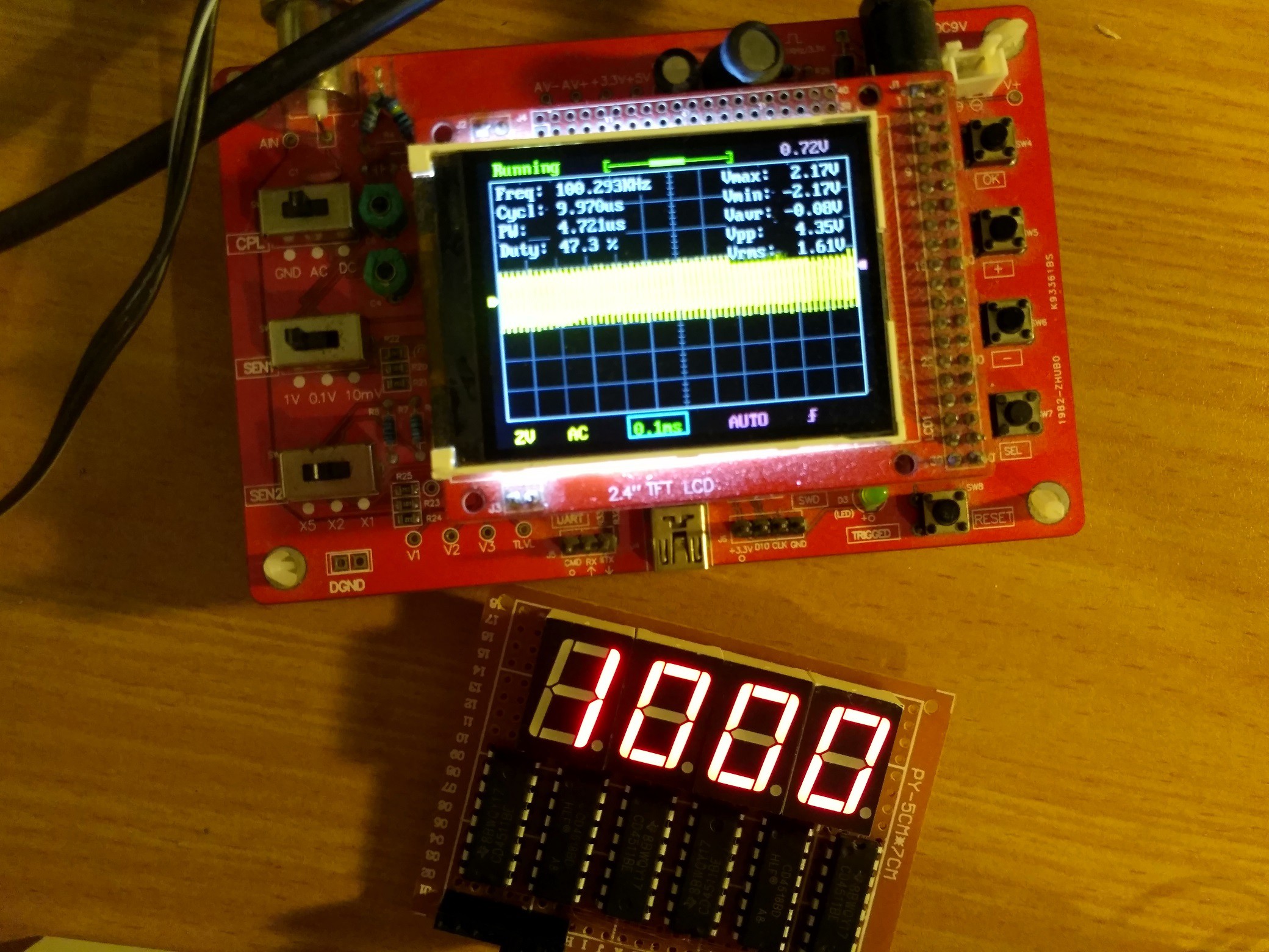
100kHz is the highest value to which I credit the chinascope's frequency measurement - higher than that and the readings fluctuate drastically. Above that I'd rather believe my own device, measuring up to 1MHz :)
Discussions
Become a Hackaday.io Member
Create an account to leave a comment. Already have an account? Log In.