BotFactory
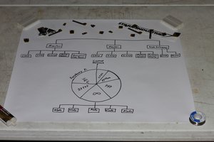
This design was printed as a single PCB and powered by a 5V AC-DC converter and a 3.3V regulator. The main component of this device is the microcontroller and transceiver combo with WiFi and Bluetooth capabilities. The microcontroller was programmed to tell the transistors which receptacle(s) should be powered. The receptacles are connected to their respective solid-state relay, which will switch the receptacles on or off when a small external voltage is supplied by a transistor. The same transistors are also used to light up the receptacle’s respective LED to let the user know if the device connected is turned on or off.
The enclosure used to house the electrical components was designed using SolidWorks and is composed of two parts—the body and the faceplate.
All of the files required to build and print this Smart Outlet can be found on our blog called Creating a Smart Outlet.

 Matej Nogić
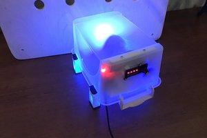
 Danya0x07
 hesam.moshiri