Close
0%
0%

Control your audio with theKnob

TheKnob - the sound volume control knob made of concrete, with RGB LED lights.

Similar projects worth following
Life is too short to adjust the sound with the mouse and not with a specially designed HID audio control device. That's why I'm an absolute fan of the idea of having specialized HID devices even for small functionalities such as audio control. There are probably many "knobs" controlling the volume of your computer. But this is not our way. The best device is this one that you can create yourself. Plus, you can always put some fun and nice-looking things in a device which is your own creation. So, driven by the idea, I began to look for some inspiration and finally found this awesome video https://youtu.be/sJ5vhShdVjo I am starting to develop.

Summary

After some thought, I synthesized the following main functions and capabilities:

  • The future device has to control audio on the PC's OS, not with just a potetiometer;
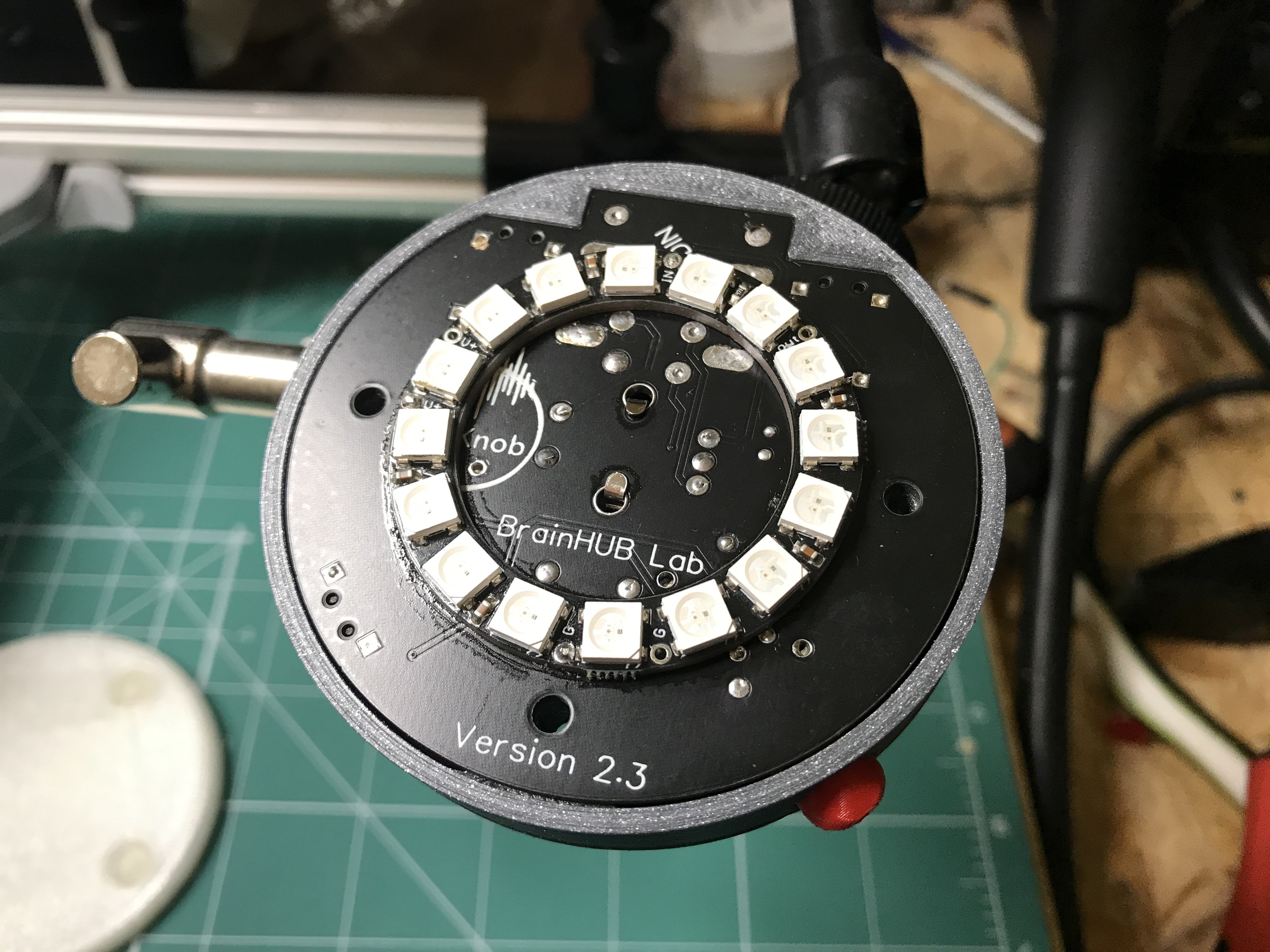
  • I want to have some nice looking RGB led lights ;
  • The future device has to be easily repeatable;
  • The future device has to have the capability for more functionality - for example scrolling;

To be honest, the presented version is already the second one, but I will describe it anyway because I loose all photos from the first one.

So, the final device has the following functions:

  • Audio control on OS by using the awesome HID library;
  • After-a-double-click the knob enters to the scroll mode;
  • There are two outputs and one input, and a physical switch between them;
  • Several LED backlight modes inclusive responsive to music (like VU meter);
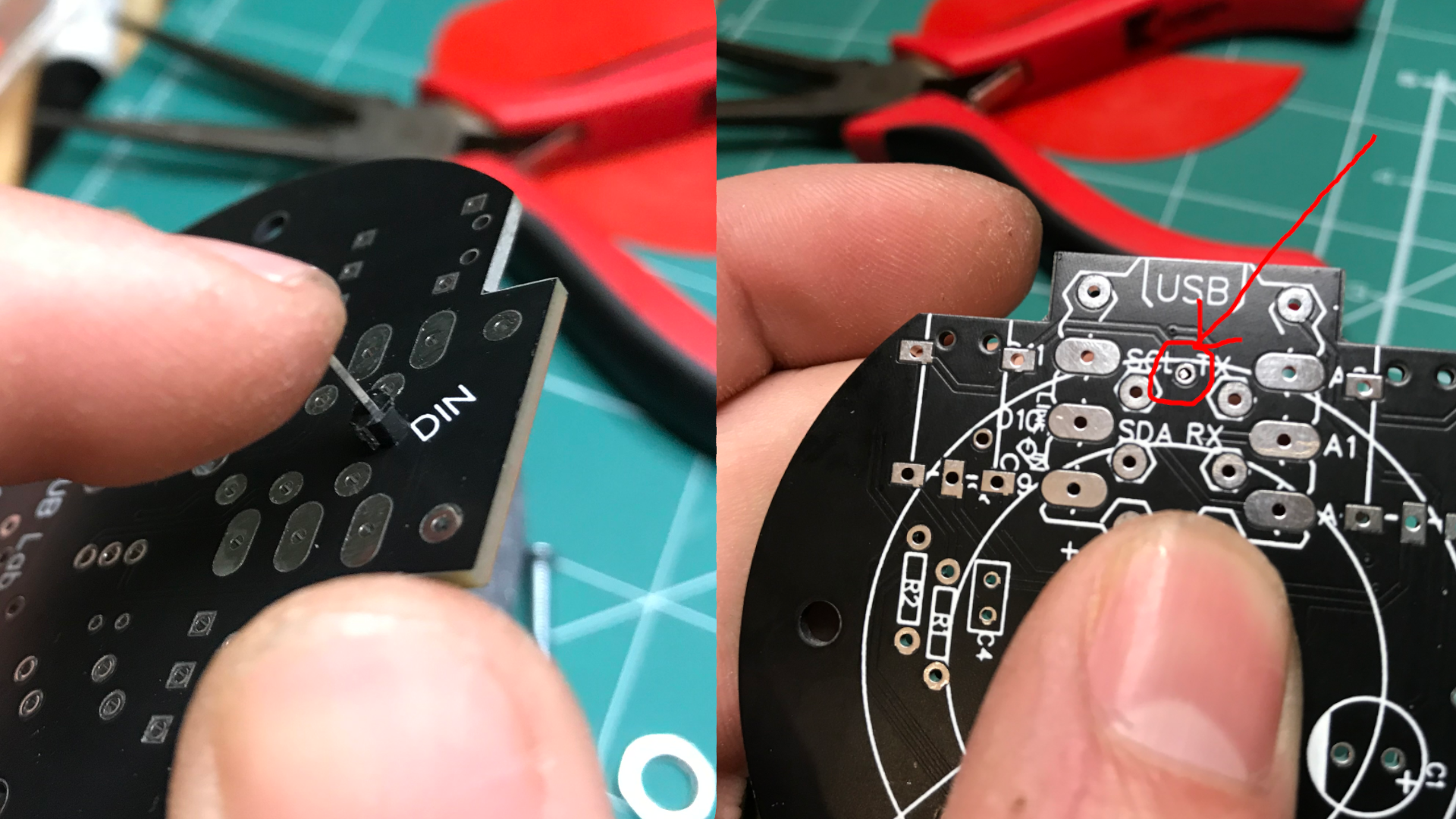
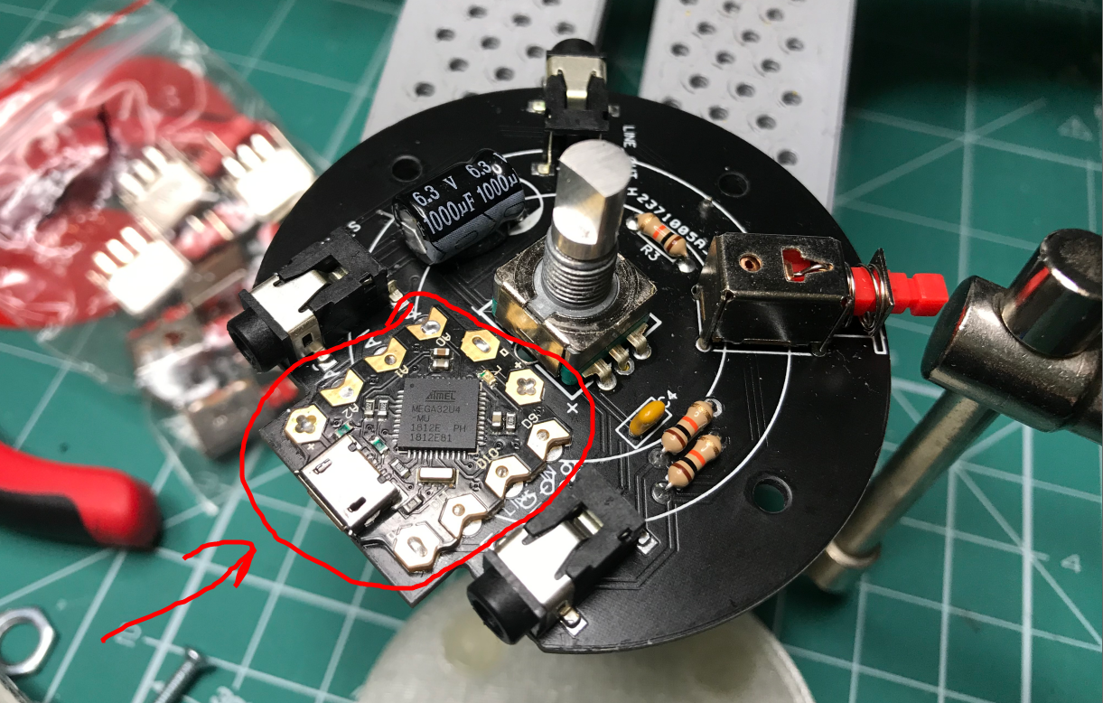
  • The code and the hardware used are simple and can be easily modified;
  • And of course, the knob is made of concrete;

View all 12 components

  • 1
    First, let's talk about the board and everything that will be necessary for it.

    The PCB itself is an extension PCB for a microcontroller board "DFrobot beetle". It allows us to keep everything in place and make it compact and also, it's easy to solder everything. 

    Please follow the steps strictly, because the design of the corpus is made a little bit tricky for assembling. It's because I want to make everything compact and optimized for 3D printing.

    If someone will write to me later I can model and add easier to assembly corpus. 

    1. First solder one header pin for the 16 bit led ring. It's better to do it now because later it will be covered by the microcontroller board. Align the pin tip to be as flat as possible like in the picture below.
    2. Then, put two pin headers in random drill holes on the microcontroller board (to adhust the position), and put some flux then drop a little soldering on the rest of the pads. Then remove the header pins and solder the rest. It's important to solder everything tightly. (The picture is only for reference )
    3. The next step is to solder all and this is important all of the passive components like resistors, capacitors, etc. (do not solder the jacks switch and encoder).
    4. Then solder the pin headers for the 16 bit LED ring.
    5. Then solder the audio channels switch.
    6. And now the most difficult part. First, put the audio jacks and the rotary encoder to the previously 3D printed corpus. Then gently put the PCB on top of them. The audio jacks will have positioning pins they must match in the holes on PCB. You can gently adjust the audio jack before soldering.  And now you are ready to solder the audio jack with more flux solder every pad of the jack and rotary encoder.  Before jumping to the next step please test all of the jacks by connecting the audio source to the input jack and test each output by switching the channels with switch. (It's important to test it now).  
    7. And the last step is to solder the 16 bit LED ring. Gently slide in the LED ring to previously solder header pins. Then drop a little soldering to them.
  • 2
    Тhen about the case

    The corpus consists of two parts: the PCB enclosure and the light disperser. In previous steps, you already put the PCB in the enclosure. Now you only need to tighten the three screws. 

    Put the 3D printed switch cap on its place and glue the rubber pads on the bottom side.

  • 3
    Аnd at the end about concrete

    For the concrete knob I already modeled the needed part. You have only to choose the right proportions or to buy ready to use concrete mixture.

    I buy the ready to use one. The mold for the concrete consists of two parts. Before putting the concrete mixture in the mold treat it with some oil. 

    When you create the concrete mixture, put a few drops of PVA glue in water before mixing.

    After about 10 hours when the concrete has not dried but is hard enough, gently remove the mold. Then place the concrete knob in an airtight envelope for the next few days.

    After the concrete knob drying is finished glue it with two-component glue to the rotary encoder. To glue it, simply apply a thin layer of glue in the hole. Use the 3D printed pad for adjustment of the knob. And without removing the pad, press with something heavy until the glue dries.

View all 4 instructions

Enjoy this project?

Share

Discussions

RunLinuxPls wrote 07/23/2020 at 03:04 point

I really appreciate your design considerations. I'd been considering a similar device but hadn't decided on hardware/form. This is gorgeous, thanks for sharing.

  Are you sure? yes | no

BrainHUB Lab wrote 08/23/2020 at 11:59 point

Thanks for the kind words :) . 

We have not picked the most successful hardware, but the easiest one to repeat and program in Arduino ecosystem.

  Are you sure? yes | no

Similar Projects

Does this project spark your interest?

Become a member to follow this project and never miss any updates