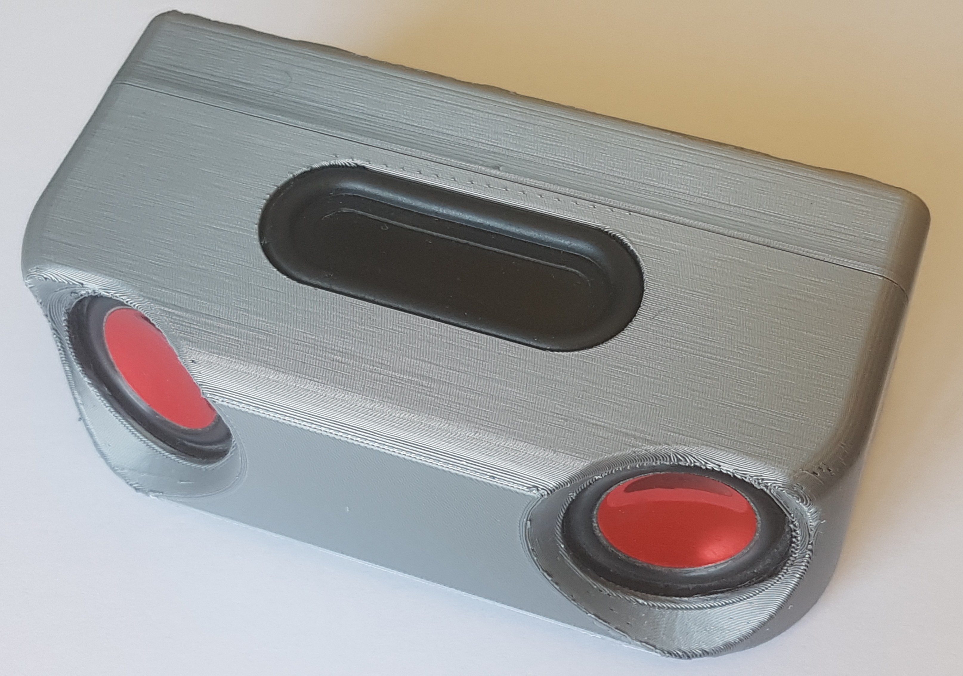
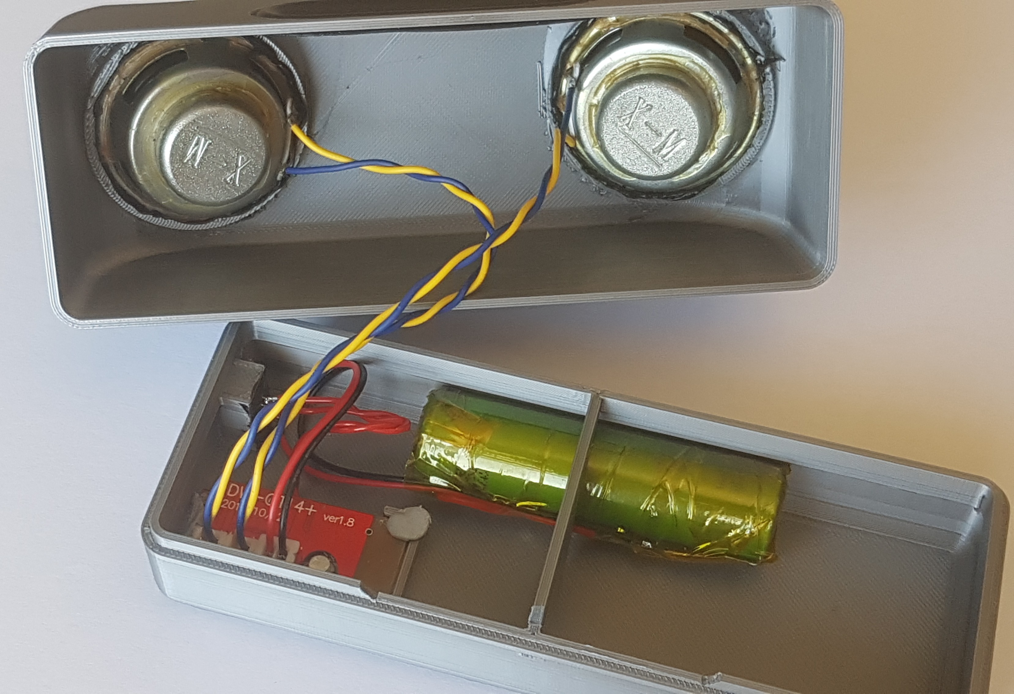
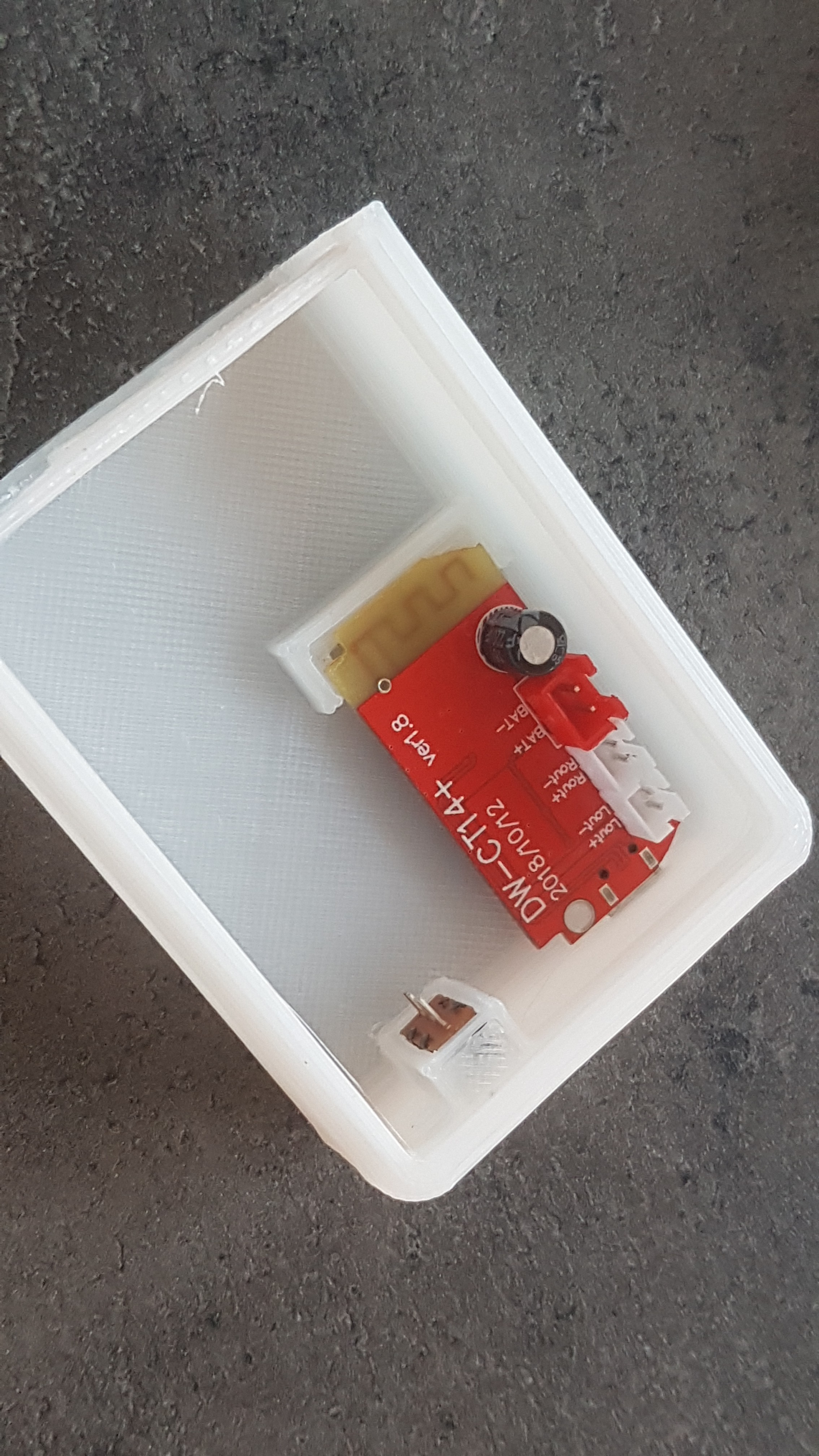
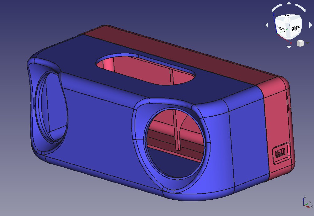
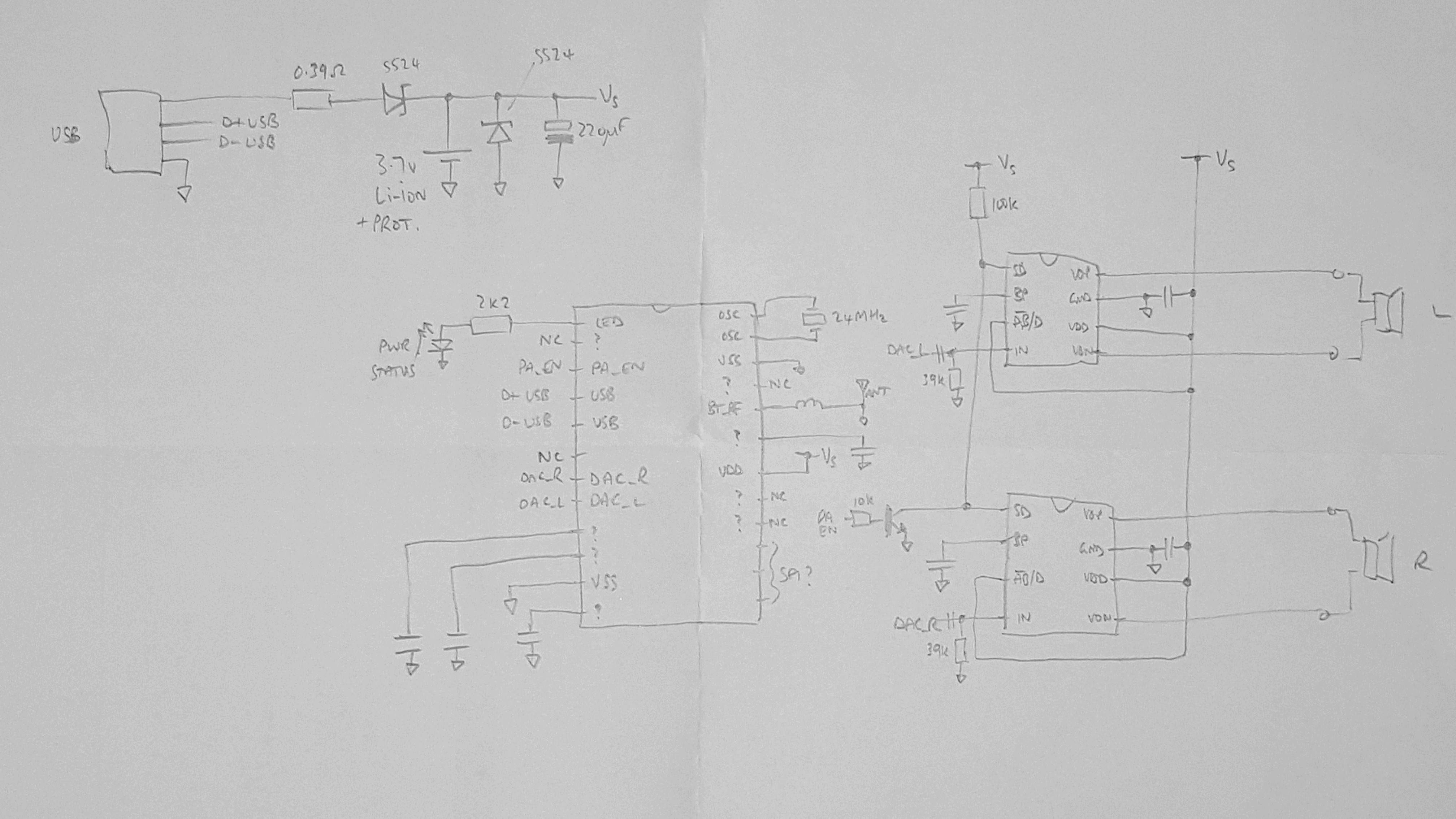
• Case ready

    RobG06/25/2020 at 11:13 0 comments

    Thanks to a friend with a Prusa, I now have a case!

    The fully-assembled speaker box.

    ...with internals glued/sealed in with silicone to make it air-tight, including round the power switch and USB socket.

    The view of its insides.

    Before I completely seal the two halves, I want to:

    - try it out for a few weeks to see how often it gets used and how

    - sort out the battery charging - which is clearly non-existent and borderline dangerous

    - add a bass-boost filter to the inputs to the amplifiers to compensate a little for the lack of box volume and driver efficiency

    - maybe even swap out the board for another that doesn't have awful (and loud!) Chinglish voice announcements, in favour of a nice 'bing-bong' or something.

  • Case design nearing completion

    RobG06/13/2020 at 20:00 0 comments

    Been busy drawing up the rear case in FreeCAD, and I'm starting to get the hang of it now. Here's a partial print so I can check everything fits ok before I commit to the real thing:

    Battery goes in the gap at the bottom but didn't quite fit...

    Complete case looks like this:

  • Switching the module off

    RobG06/06/2020 at 13:52 0 comments

    The board is labelled v1.8, which seems to be less common on the web than the v1.6 and v1.7. The differences seem to be to do with controlling the amplifiers' SD pins - everything else looks pretty much identical.

    The amp chips have a shutdown pin (pin 1) which appears to be active high: pulling it low or leaving it floating turns the amp on. As standard they are controlled via an NPN transistor (S8050) level-inverter from the BT module (pin 3), as evidenced by the slight pop when starting/stopping audio.

    The BT chip itself doesn't appear to have an enable/shutdown pin (at least the AC6905 doesn't).

    Charging is really simple: 5V from the USB connector is dropped first through a 0.39ohm current limit resistor, then through a SS24 Schottky diode (~0.5-0.6V) and then connected to the Li-ion cell. That's why the cell needs protection: because the charge circuit can float up to ~4.5V, higher than is safe for Li-ion. Charging from flat (e.g. 3.0V) is slightly terrifying: about 1.3V gets dropped across the 0.39ohm resistor, meaning the charge current is 3.3A! That's about 2.4C charge rate for my single 18650 cell. Eeek. Also about 4W gets dissipated by the tiny chip resistor - that'll get pretty toasty I bet. Ah, but of course USB is limited to about 100mA for a standard peripheral, so this circuit relies on the USB host doing the current limiting correctly. Still eeeek.

    The obvious place to insert a power switch, therefore, is just downstream of the battery/charging, but before the BT and amplifiers. Sounds simple, but the layout is a bit inconvenient.

    Rough schematic of CT14 module

    I had a go at tracing out the schematic, see above.

  • First look at BT/amp module

    RobG06/05/2020 at 17:51 0 comments

    I chose the "DW-CT14" module, found all over eBay and Amazon. It's got a Bluetooth 4.2 chip, two amplifiers and circuitry for charging a 3.7 Li-ion cell (as long as it has protection).

    The amplifiers (NS4165) are capable of more than 5W into 2ohm, but into 4ohm can only manage 3W (from a 5V supply) or a measly 1.8W from the 3.6V I'll have from my single Li-ion cell. So those listings that advertise the module as "5W+5W" are a little way off! The chip can be switched between class AB and class D and, thankfully, they do appear to be configured for class D. Earlier versions of the module seem to use the TC8871 instead, which is a pin-equivalent part.

    The BT module is in a 24-pin SOP packaged marked "AS19AP" which seems to make it one of the ubiquitous JieLi ("Jerry") family, but it's not clear which. It's not an AC9605, judging by the pinout which is different. The USB micro B port powers it (and charges the cell), and its data lines are connected to the chip, but no device appears when connected to a PC, so perhaps it needs putting into a special mode (as described here for other similar parts). There are three test pads connected to pins 13, 14 and 15 which I suspect are CLK, MOSI and MISO - might be fun to try connecting at some point.

    The whole module draws 14mA when paired but not playing, and 41mA when playing at minimum volume. 30mA of this would appear to be the two amplifiers if the datasheet is to be believed. From my 1400mAh cell I should easily get a day's play time unless I run it quite loud. Four days if I don't play any audio (i.e. just BT).

    Li-ion charging current is approx. 125mA (measured with a nearly-full cell).

    As a first test run, I 3D-printed a partial enclosure, Blu-tacked the speakers in and wired everything up. Despite the puny output power, the whole thing does seem to be reasonably loud - enough for a picnic but not a party. The worst part is the awful Chingrish announcements when switching on. Surely a short beep would have sufficed?

    I'll probably want to switch the module off to conserve battery. The obvious way to do this would be to interrupt the connection to the battery, but this means it can't charge unless it's switched on. I might see if I can bodge a way to put the BT and amplifiers into standby, rather than powering-off the whole circuit.