The first log contains a detailed description of the design.
0%
0%
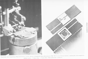
VGA video generation card
16 bit VGA interface, 32K colors, graphic 640x480, sprites, sound, intended for Kobold K2 computer, no special video chips.
Become a Hackaday.io member
Already have an account? Log in.
Just one more thing
To make the experience fit your profile, pick a username and tell us what interests you.
Pick an awesome username
hackaday.io/
Your profile's URL: hackaday.io/username. Max 25 alphanumeric characters.
Pick a few interests
Projects that share your interests
People that share your interests
 zpekic
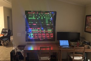
 spudfishScott
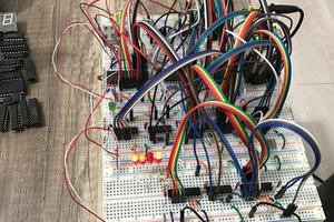
 Dr PEKER
 Anders Dinsen